Pico serial bootloader
Serial bootloader for the Raspberry Pi Pico (RP2040)
My Pi Wars 2022 entry, M0o+, is powered by a Raspberry Pi Pico, which itself is powered by the RP2040 chip.
The RP2040 has a built-in boot ROM with a USB bootloader, which allows the chip to show up as a USB flash drive for uploading code. This is usually a very convenient interface, making it extremely quick and simple to upload code to the device.
However, in a Pi Wars robot, I don’t want to have to bring the Pico back to my computer and plug it in to iterate on the code - I see it as essential to be able to download new code to the robot wirelessly without needing to touch it.
I knew I’d be using an ESP32 to provide Bluetooth connectivity, and so decided to write a simple serial bootloader which allows code upload to the Pico via a UART, and then use the ESP32 as a WiFi-to-UART bridge to upload code wirelessly.
What’s a bootloader?
A bootloader is a program whose purpose is to load (and run) other programs. They run as one of the first things on boot and load the code to run.
Bootloaders are often described in terms of stages. Typically the “first stage bootloader” is difficult or impossible to change (for example, baked into non-modifiable ROM), and is therefore kept very simple to minimise the potential for bugs.
The job of the first stage is just to start the next stage. The next stage might be the program itself, or it might be another (“second stage”) bootloader, which is more complicated/capable and (crucially), modifiable.
On a “full size” Raspberry Pi, there’s a “first stage” bootloader baked into
some ROM in the chip. It has one job: find the second stage bootloader
(bootcode.bin) on the SD card1 and run it. The second stage bootloader has
a lot more capability, it provides functionality like USB and network boot, as
well as understanding config.txt.
Its job is to load the next stage -
usually the Linux kernel - and boot that. Because the second stage is on the SD card,
it can be modified, fixed and updated easily, and this has been used
throughout the Raspberry Pi’s life to add functionality even to devices with
“old” chips.
Pico boot sequence
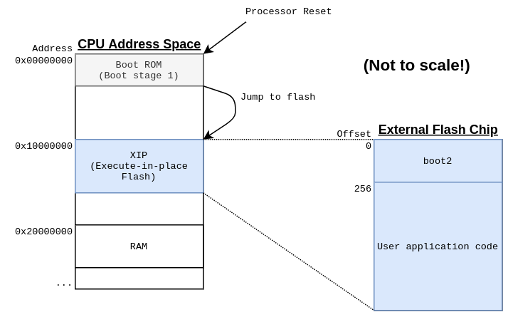
As mentioned above, the Pico also has a first stage bootloader baked into ROM2. This is always the very first thing that runs when the RP2040 starts up, and after the physical chip is manufactured, it can never be changed.
The built-in bootloader has a fixed sequence, described in full in the datasheet.
In summary, it checks if the BOOTSEL button is pressed, and if so, enters the
USB mass storage mode for code upload. If the BOOTSEL button is not pressed,
and it looks like the flash contains a valid program, then it starts executing
the “program” from flash.
The Pico SDK actually puts a second stage bootloader at the start of every
program (called boot2), which we’ll discuss further below, so when the first
stage starts your program, what it’s actually doing is starting boot2, and
then that will start the program.
My bootloader will act like a “third stage” bootloader, executing after boot2
and allowing code to be uploaded over UART, before finally executing
the actual program.
Second stage bootloader: boot2
Unlike more traditional microcontrollers, the RP2040 uses an external flash chip to store program code. This has become more common in recent years, with notable other examples being the ESP8266 and ESP32 chips from Espressif.
The RP2040 datasheet says:
RP2040 is a stateless device, with support for cached execute-in-place from external QSPI memory. This design decision allows you to choose the appropriate density of non-volatile storage for your application, and to benefit from the low pricing of commodity Flash parts.
This presumably helps keep the size (and therefore price) of the RP2040 chip down and allows a single chip variant to serve different applications (through different sizes of flash chip). I suspect that there are also technical reasons not to put the flash on the same silicon die as the logic, which may factor in to the decision not to put any flash in the RP2040.
There is a standard3 for SPI flash chips, which makes it possible to read data
from almost any flash chip using the same protocol. This protocol is baked in
to the Pico bootrom, allowing it to read the second stage boot2 bootloader
from flash, without needing to know what specific brand or size of flash
is connected.
However, different flash manufacturers and products have different protocols for
configuring their chips to provide the best performance for reading and executing code.
boot2’s job is to know which specific flash chip is connected, and exactly
how to properly configure it for high speed, efficient, code access.
It wouldn’t be sensible to put this chip-specific flash setup code into the hard-coded, non-modifiable boot ROM on the chip, because then the variants of flash chip that can be supported by RP2040 would be set in stone.
Instead, when you build a program in the Pico SDK, it selects an appropriate
second stage bootloader based on what kind of board you are building for.
There are several versions of boot2 for different flash chips, and each
one is exactly 256 bytes of code which is put right at the start of the eventual
program binary. This code configures the flash chip using the appropriate
commands for that specific chip, and then runs the main program which directly
follows boot2 in flash.
Bootloader implementation
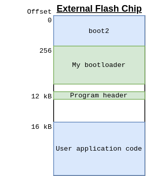
I’ve prioritised simple code and ease of development over minimising the size of my bootloader, and as a result it takes up nearly 12 kB of flash!
The flash can only be erased in 4kB chunks, so the first 12 kB (3 chunks) of
flash are used for boot2 and my bootloader, followed by a 4 kB page (1 chunk) which
stores an image header describing the program, and then the program can be
written to any other area of flash (for example starting at 16 kB in the diagram
below).
It is absolutely possible to write a serial bootloader for the Pico in a fraction of this size - for example I found this example (rhulme/pico-flashloader) which looks like it was being written about the same time I was writing mine, and fits in < 4 kB; or this one (dwelch67/raspberrypi-pico/bootloader10) which is very minimal indeed.
When I started out, as is often the case, I couldn’t find anything which met my requirements, so I invented my own. The code is available on GitHub.
Mine implements a simple command state machine, with a set of commands to enable erasing, writing, reading and verifying the flash. The Pico SDK provides helper functions for flash erasure and programming, making that part straightforward.
Similar to the bootrom first stage bootloader, mine will enter programming mode if a button is pressed, if some special values are present in the watchdog registers, or if there is no valid program already loaded.
The actual program can be written anywhere in flash (as long as it’s not in the first 16 kB), and an image header is stored which describes the start address and size of the program, and a CRC checksum of its data for validation. This image header is what the code uses to determine if there’s a valid program to be run.
The command set is relatively simple:
CMD_SYNC
The bootloader is using a UART, so there’s no synchronisation like SPI chip-select or i2c start conditions, so there needs to be a way for the “host” and the Pico to synchronise.
The CMD_SYNC command exists for this purpose. The idea is that the host just
keeps sending the 4 bytes SYNC over and over until the bootloader replies:
PICO.
Whenever the bootloader encounters an error state, it goes back to “sync” mode, and it won’t do anything until the host re-synchronises.
CMD_READ
This isn’t actually used for anything in my eventual set-up, but it was the first command I implemented because it’s simple.
CMD_READ has two arguments: An address and a size. It will simply return
the data from that address.
The total transfer size is limited to 1024 bytes, so you can only read up to 1 kB at a time.
CMD_CSUM
CMD_CSUM takes two arguments: address and size, and computes a checksum. It
uses the RP2040’s DMA engine “sniffer” to add up all of the values of all of
the bytes in the provided range, and returns the result (modulo 2^32).
Initially I couldn’t get the sniffer CRC to match a “reference” implementation, so I implemented this as a stop-gap. That issue turned out to be my own mistake.
This is/was used to check the integrity of data transferred.
CMD_CRC
Just like CMD_CSUM, but instead of a checksum, it computes a CRC. Still using
the DMA sniffer. It calculates values matching the IEEE802.3 CRC algorithm,
which seems widely supported (e.g. the crc32 command-line utility, the go hash/crc32
library).
CMD_ERASE
Erases a page of flash. Takes an address (which must be in the “XIP” region) and a size to erase. The address and size must be aligned to the flash “sector size”, which is 4 kB.
It doesn’t let you wipe the bootloader itself.
CMD_WRITE
This is the real business function. It writes data to flash, given an address (which must be in the “XIP” region), size and data. The address and data length must be aligned to the flash page size - 256 bytes. The maximum data length is 1 kB.
After writing the data, this calculates the CRC of the written data and returns it, so that the host can determine if everything was written correctly.
CMD_SEAL
This is how the host indicates that it’s done writing a program and sets the program header.
The host provides:
- The program start address
- The program length
- The expected CRC of the program
The implementation will calculate the CRC of the specified program range, and if successful, store the settings as the program header.
CMD_GO
CMD_GO just jumps to an address provided by the host. It has one argument:
the address. It performs no validation, just resets a bunch of peripherals,
sets the VTOR to the provided address, and jumps!
CMD_INFO
CMD_INFO lets the host query the parameters it needs to know to be able to
use the bootloader:
- Flash (XIP) start address
- Flash size
- Erase alignment (4 kB)
- Write alignment (256 btyes)
- Max data length (1024 bytes) (not including command opcode and arguments)
CMD_REBOOT
This triggers a reboot. It takes one argument - if the argument is non-zero then it sets the watchdog registers to stay in the bootloader, instead of starting the user application (if there is one).
Host side
On the “host” side, I’ve written some go code to communicate with the bootloader, including a simple command line
application allowing writing an .elf or .bin file over a serial port.
There’s not too much to say about this. The application is used like so:
./serial-flash /dev/ttyUSB0 firmware.elf
…but really, I’m just using the library functions it implements and embedding the functionality in my UI application (a future post!).
Building programs to work with the bootloader
As described above, the Pico SDK by default places boot2 at the start of the
program binary, and will build the program so that it expects to run from the
start of flash.
To make programs compatible with my bootloader, we need to skip adding boot2 (not
strictly necessary) and set them up so that they can be written to a section of
flash after my bootloader (starting at least 16 kB from the start of flash).
This is easy to do with a custom linker script, which differs from the default one in two ways:
- Modify the FLASH configuration to set the start address to 16 kB, and the size to (2 MB - 16 kB)
- Don’t add
boot2
diff --git a/pico-sdk/src/rp2_common/pico_standard_link/memmap_default.ld b/blink_noboot2.ld
index 07d5812..448f834 100644
--- a/pico-sdk/src/rp2_common/pico_standard_link/memmap_default.ld
+++ b/blink_noboot2.ld
@@ -21,9 +21,10 @@
     __stack (== StackTop)
 */

+/* Skip 16kB at the start of flash, that's where our bootloader is */
 MEMORY
 {
-    FLASH(rx) : ORIGIN = 0x10000000, LENGTH = 2048k
+    FLASH(rx) : ORIGIN = 0x10000000 + 16k, LENGTH = 2048k - 16k
     RAM(rwx) : ORIGIN =  0x20000000, LENGTH = 256k
     SCRATCH_X(rwx) : ORIGIN = 0x20040000, LENGTH = 4k
     SCRATCH_Y(rwx) : ORIGIN = 0x20041000, LENGTH = 4k
@@ -33,30 +34,11 @@ ENTRY(_entry_point)

 SECTIONS
 {
-    /* Second stage bootloader is prepended to the image. It must be 256 bytes big
-       and checksummed. It is usually built by the boot_stage2 target
-       in the Raspberry Pi Pico SDK
-    */
-
     .flash_begin : {
         __flash_binary_start = .;
     } > FLASH

-    .boot2 : {
-        __boot2_start__ = .;
-        KEEP (*(.boot2))
-        __boot2_end__ = .;
-    } > FLASH
-
-    ASSERT(__boot2_end__ - __boot2_start__ == 256,
-        "ERROR: Pico second stage bootloader must be 256 bytes in size")
-
-    /* The second stage will always enter the image at the start of .text.
-       The debugger will use the ELF entry point, which is the _entry_point
-       symbol if present, otherwise defaults to start of .text.
-       This can be used to transfer control back to the bootrom on debugger
-       launches only, to perform proper flash setup.
-    */
+    /* boot2 would go here, but we don't want it */

     .text : {
         __logical_binary_start = .;
You can tell the SDK to use this custom linker script with the pico_set_linker_script command in CMakeLists.txt:
pico_set_linker_script(blink_noboot2 ${CMAKE_CURRENT_SOURCE_DIR}/blink_noboot2.ld)
I’ve put a simple “blinky” example which is compatible with my bootloader on GitHub here: https://github.com/usedbytes/pico-blink-noboot2
Next…
So this all allows me to upload code over UART. The next step is to hook the UART up to an ESP32, allowing code upload over WiFi, which will be the next post.
-
The Raspberry Pi 4 is slightly different, having the second stage bootloader in an EEPROM instead of on the SD card. ↩︎
-
Note that the ROM contains other code in addition to the first stage bootloader. Things like optimised mathematical routines and flash programming functions. ↩︎
-
I can’t find a decent reference for what that standard actually is, but it’s referred to as “Standard SPI” in various places, and everyone seems to have agreed on how it works. ↩︎