Reverse Engineering keyboard firmware with Ghidra - Part 2
Last time, in Part 1, we found out the super-secret XOR key for the Ducky One firmware updater and used it to obtain its file header describing the firmware version and keyboard layout.
The next missing piece to find is the size of the firmware image, which will
tell us which part of the .exe file contains the firmware.
To find out where to look, we need to go back to the xx_get_fw function,
which takes the firmware size as a parameter:
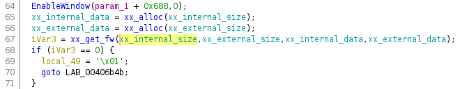
Unfortunately, if we look specifically at the xx_internal_size parameter,
Ghidra only finds read accesses and no writes. The two unnamed references are
the actual write and verify operations:
At this point, I have a confession and apology to make: In the previous post,
I was working on the V1.01 firmware update, and in this post we’ve switched
to V1.03. This is for reasons which will be discussed later, but for now, they
are similar enough that everything from last time still applies.
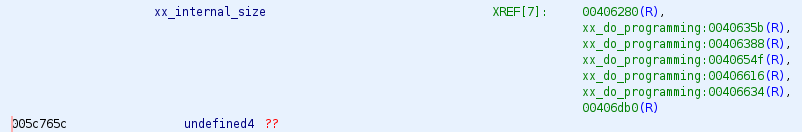
Given that xx_internal_size isn’t in the initialised data section of the
.exe, it must be initialised at runtime, which means it’s probably read from
some section near the end of the file just like the file header and firmware
are. Given that the header and the firmware both also go through the “secret
key” decryption process, let’s take a look at xx_secret_key again:
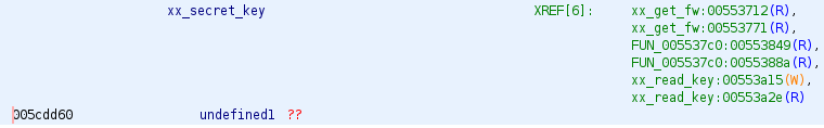
It’s accessed in three places: xx_get_fw, where we’ve already established it’s
used to “decrypt” the firmware image, xx_read_key which is the function that
reads the key and file header, and FUN_005537c0. So, let’s take a look at that
one.
Chunks 1 and 2
void FUN_005537c0(void *param_1,void *param_2)
{
	byte *pbVar1;
	DWORD DVar2;
	uint uVar3;
	byte bVar4;
	uint uVar5;
	FILE *local_214;
	wchar_t local_210 [260];
	uint local_8;

	local_8 = DAT_005c14f0 ^ (uint)&stack0xfffffffc;
	DVar2 = GetModuleFileNameW((HMODULE)0x0,local_210,0x104);
	if (DVar2 != 0) {
		__wfopen_s(&local_214,local_210,L"rb");
		FUN_00553630(local_214);
		FUN_0053ab84(local_214,0xfffffd68,2);
		_fread(param_1,1,0x10,local_214);
		uVar5 = 0;
		do {
			pbVar1 = (byte *)((int)param_1 + uVar5);
			uVar3 = uVar5 & 3;
			bVar4 = (byte)uVar5;
			uVar5 = uVar5 + 1;
			*pbVar1 = (&xx_secret_key)[uVar3] ^ *pbVar1 ^ bVar4;
		} while (uVar5 < 0x10);
		FUN_0053ab84(local_214,0xfffffd58,2);
		_fread(param_2,1,0x10,local_214);
		uVar5 = 0;
		do {
			pbVar1 = (byte *)((int)param_2 + uVar5);
			uVar3 = uVar5 & 3;
			bVar4 = (byte)uVar5;
			uVar5 = uVar5 + 1;
			*pbVar1 = (&xx_secret_key)[uVar3] ^ *pbVar1 ^ bVar4;
		} while (uVar5 < 0x10);
		_fclose(local_214);
		FUN_00538ac2();
		return;
	}
	FUN_00538ac2();
	return;
}
It’s a familiar pattern at this point. Open the file, seek to somewhere near the end, read and “decrypt” some data. It does this twice for two different “chunks”.
The first chunk is at 664 bytes from the end of the file (0xfffffd68 is
-664 in two’s complement,
which is how all modern computers represent signed integers), and the second is
16 bytes earlier at 0xfffffd58 or -680.
This is where a slight difference between V1.01 and V1.03 arises - in
V1.03, -664 is exactly 16 bytes before the start of the “header + key” block.
In V1.01 the header is a little smaller.
So, in summary what we see here are two 16-byte chunks being read (for the sake
of argument, xx_chunk1 and xx_chunk2. If we label those up, and check where
they are in the memory map, we can see that xx_internal_size is bytes 4-7 of
xx_chunk1!
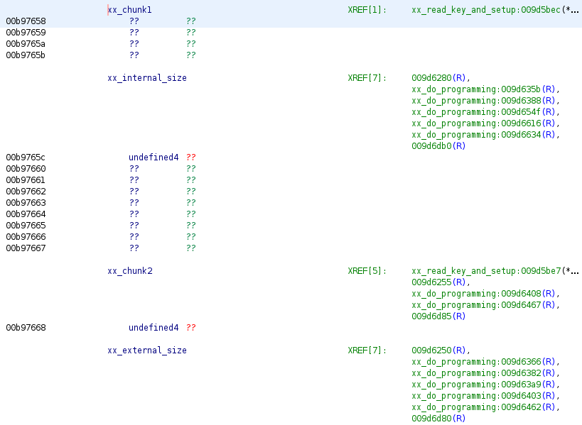
Copying the “read two chunks” code into my C test program, I can read and decode
the two chunks and get a value for xx_internal_size: 0x56e0, or 22240 bytes.
Firmware blob
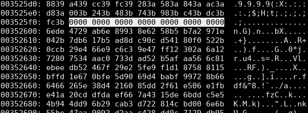
This finally tells us that the firmware is 22240 bytes long, and starts at (22240 + 680) bytes from the end of the file. In a hex editor, this looks promising. The suspected firmware is preceeded by a string of zeroes which looks a lot like padding:
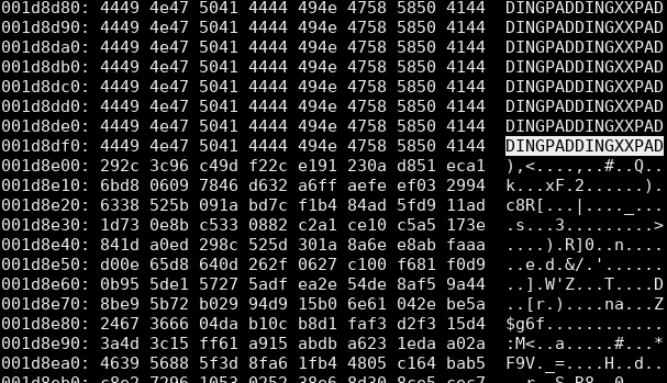
In fact, in the V1.01 file, instead of zeroes it literally contains the letters
“PADDINGXX”:
Now we can put the xx_get_fw code into the test program, and read and
“decrypt” the firmware. Giving us a blob of data which starts like this:
00000000: 84be c2c7 450a 0879 6c0a d553 51ce 1efc  ....E..yl..SQ...
00000010: fe5b e848 e9c1 3c77 3b74 48b7 768c cbd9  .[.H..<w;tH.v...
00000020: c68b 8c2a a8ad 6709 5c0f 52d4 f666 c3d0  ...*..g.\.R..f..
00000030: a8d0 c0ea 7494 c2e7 7f0a 0879 7c0a d553  ....t......y|..S
00000040: 41ce 1efc e85b e848 fdc1 3c77 2174 48b7  A....[.H..<w!tH.
00000050: 05cd cbd9 b5ca 8c2a dbec 6709 2f4e 52d4  .......*..g./NR.
00000060: ee66 c3d0 b6d0 c0ea 07d5 c2e7 630a 0879  .f..........c..y
00000070: 7e0a d553 41ce 1efc e85b e848 fdc1 3c77  ~..SA....[.H..<w
00000080: 2174 48b7 05cd cbd9 b5ca 8c2a dbec 6709  !tH........*..g.
00000090: 2f4e 52d4 ee66 c3d0 b6d0 c0ea 07d5 c2e7  /NR..f..........
000000a0: 630a 0879 7e0a d553 328f 1efc e85b e848  c..y~..S2....[.H
000000b0: fdc1 3c77 2174 48b7 05cd cbd9 b5ca 8c2a  ..<w!tH........*
000000c0: dbec 6709 2f4e 52d4 ee66 c3d0 b6d0 c0ea  ..g./NR..f......
000000d0: 07d5 c2e7 104b 0879 0d4b d553 328f 1efc  .....K.y.K.S2...
000000e0: 9b1a e848 afc6 3c77 7772 48b7 05cd cbd9  ...H..<wwrH.....
000000f0: b5ca 8c2a dbec 6709 2f4e 52d4 ee66 c3d0  ...*..g./NR..f..
This is not what I was hoping to see.
You see, firmware for the Cortex-M3 microcontroller in the keyboard usually starts with a special layout:
00000000: Initial stack pointer
00000004: Reset vector
00000008: NMI vector
0000000C: Hard fault
00000010: Memory management fault
00000014: Bus fault
00000018: Usage fault
0000001C: Reserved
...
This is the vector table, and
is a list of pointers to interrupt service routine functions which should
happen on “Reset”, non-maskable interrupt (“NMI”), “Hard fault” etc. The very
first 4-byte world should be the initial stack pointer - and in most Cortex-M3
designs, RAM starts at 0x20000000, so we’d expect to see something like 0x20
in the fourth byte. This is not what we see.
To show what it should look like, we can look at the start of some Cortex-M3
firmware that I compiled myself. This clearly shows the initial stack pointer
(0x20005000) followed by a very structured table of pointers to the various
interrupt service routines.
00000000: 0050 0020 d112 0008 cf12 0008 410a 0008  .P. ........A...
00000010: cd12 0008 470a 0008 4d0a 0008 0000 0000  ....G...M.......
00000020: 0000 0000 0000 0000 0000 0000 cf12 0008  ................
00000030: cf12 0008 0000 0000 cf12 0008 bd0a 0008  ................
00000040: cd12 0008 cd12 0008 cd12 0008 cd12 0008  ................
00000050: cd12 0008 cd12 0008 cd12 0008 cd12 0008  ................
00000060: cd12 0008 cd12 0008 6907 0008 cd12 0008  ........i.......
00000070: cd12 0008 cd12 0008 cd12 0008 cd12 0008  ................
00000080: cd12 0008 cd12 0008 cd12 0008 cd12 0008  ................
00000090: cd12 0008 cd12 0008 cd12 0008 cd12 0008  ................
000000a0: cd12 0008 cd12 0008 cd12 0008 cd12 0008  ................
000000b0: cd12 0008 cd12 0008 cd12 0008 cd12 0008  ................
000000c0: cd12 0008 cd12 0008 cd12 0008 cd12 0008  ................
000000d0: cd12 0008 cd12 0008 cd12 0008 cd12 0008  ................
000000e0: cd12 0008 cd12 0008 cd12 0008 cd12 0008  ................
000000f0: cd12 0008 cd12 0008 cd12 0008 cd12 0008  ................
00000100: cd12 0008 cd12 0008 cd12 0008 cd12 0008  ................
Furthermore, just throwing the extracted binary into a disassembler, it doesn’t
really look like sensible Arm (Thumb) code - the very first instruction is
allegedly a breakpoint, which I’m not sure you’d ever expect to see in compiler
output, and there are a very high number of UNDEFINED an UNPREDICTABLE
instructions:
       0:       be84            bkpt    0x0084
       2:       c7c2            stmia   r7!, {r1, r6, r7}
       4:       0a45            lsrs    r5, r0, #9
       6:       7908            ldrb    r0, [r1, #4]
       8:       0a6c            lsrs    r4, r5, #9
       a:       53d5            strh    r5, [r2, r7]
       c:       ce51            ldmia   r6, {r0, r4, r6}
       e:       fc1e 5bfe       ldc2    11, cr5, [lr], {254}    ; 0xfe  ; <UNPREDICTABLE>
      12:       48e8            ldr     r0, [pc, #928]  ; (0x3b4)
      14:       c1e9            stmia   r1!, {r0, r3, r5, r6, r7}
      16:       773c            strb    r4, [r7, #28]
      18:       743b            strb    r3, [r7, #16]
      1a:       b748                            ; <UNDEFINED> instruction: 0xb748
      1c:       8c76            ldrh    r6, [r6, #34]   ; 0x22
      1e:       d9cb            bls.n   0xffffffb8
      20:       8bc6            ldrh    r6, [r0, #30]
      22:       2a8c            cmp     r2, #140        ; 0x8c
      24:       ada8            add     r5, sp, #672    ; 0x2a0
      26:       0967            lsrs    r7, r4, #5
      28:       0f5c            lsrs    r4, r3, #29
      2a:       d452            bmi.n   0xd2
      2c:       66f6            str     r6, [r6, #108]  ; 0x6c
      2e:       d0c3            beq.n   0xffffffb8
      30:       d0a8            beq.n   0xffffff84
      32:       eac0 9474                       ; <UNDEFINED> instruction: 0xeac09474
It’s perfectly possible for the UNDEFINED things to simply be constants
but the sheer number of them seems rather high. At this point, I’m thinking that
this isn’t plain Thumb code, and something more must be going on.
Digging more
I spent a bunch more time digging through the decompilation, and wasn’t able to find anything which looked like it would further “decrypt” the firmware - as far as I could tell, the data which I’ve shown above looked like what was going to get sent over USB.
I was surprised that it didn’t look like plaintext firmware - given that it looks like the normal Holtek ISP commands are being used, I would expect the data to be a ready-to-run chunk of code.
What I did determine is the format of USB commands used. They all follow a common pattern:
| Description | Byte 0 (Command) | Byte 1 (Sub-command) | Byte 2 | Byte 3 | Byte 4 … Byte 63 |
|---|---|---|---|---|---|
| Erase All | 0x00 | 0xA | CRC Low | CRC High | Don’t Care |
| Erase Range | 0x00 | 0x8 | CRC Low | CRC High | Start Addr (32-bit), End Addr (32-bit), Don’t Care |
| Verify | 0x01 | 0x0 | CRC Low | CRC High | Start Addr (32-bit), End Addr (32-bit), Data |
| Program | 0x01 | 0x1 | CRC Low | CRC High | Start Addr (32-bit), End Addr (32-bit), Data |
| Read | 0x01 | 0x2 | CRC Low | CRC High | Start Addr (32-bit), End Addr (32-bit), Don’t Care |
| Get Information | 0x03 | 0x0 | CRC Low | CRC High | Don’t Care |
| Reset to IAP | 0x04 | 0x1 | CRC Low | CRC High | Don’t Care |
| Reset to Normal | 0x04 | 0x0 | CRC Low | CRC High | Don’t Care |
And guess what: It’s the same command-set which Sprite_tm found for his Coolermaster!
Annoyingly, the packets all include a CRC, which we’ll need to figure out in order to write our own.
To further confirm that I hadn’t done something wrong, I decided to try two further approaches: I’d use WinDbg on a Windows virtual machine to actually run the firmware updater and trace what happened, and use Wireshark to capture all the USB traffic during the firmware update.
This is the reason that I had to switch from V1.01 to V1.03 - the V1.01
updater I have is for a 108-key US keyboard, and I have an EU layout, so the
updater refused to run, and I needed to use the V1.03 EU version.
WinDbg
WinDbg is a debugger from
Microsoft,
which I’d never used before but works more-or-less the same as gdb just with
different commands.
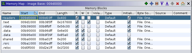
Loading the firmware updater into WinDbg, the first issue I hit was that none
of the addresses I saw in Ghidra were valid. The problem turns out to be that
the image load address isn’t the 0x00400000 which Ghidra assumes, it was
0x009d0000 (shown in WinDbg via the lm command). I’m assuming this is due
to Address Space Layout Randomisation
(ASLR). The
whole image is shifted, so in Ghidra’s memory map screen we can just move the
base address to 0x009d0000 and we won’t need to do any translation by hand.
Running through the program, placing breakpoints at various places, I was pleased to see that all of my conclusions so far had been correct. The secret key, image size, chunks and even firmware contents was exactly what I had identified.
What was most interesting to me was that the nonsense binary data above is exactly what is written to the USB file.
Wireshark
I am running Windows in a virtual machine under Linux, which means that all of the actual USB traffic is going through the Linux kernel. We can use Wireshark to capture all the USB traffic, to be absolutely certain what’s being sent to the keyboard.
This was straightforward, and I captured a full firmware update session.
We can see final confirmation that the “nonsense” firmware data is exactly what’s being transferred over USB to the keyboard (also confirming my command format decoding from above). Here we see the first “Program” packet:
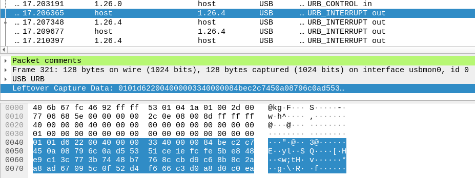
Which is decoded like so:
0x0000: 0x01 # Command - Program
0x0001: 0x01 # Sub-command - Write (not verify)
0x0002: 0x22d6 # CRC
0x0004: 0x00004000 # Start address
0x0008: 0x00004033 # End address
0x000C: 84 be c2 c2 c7 ... # Data
We can see that the data 84 be c2 c7 matches what we pulled out from the
.exe. Also of note is the start address - 0x4000. This is queried from the
keyboard with ISP_GetInformation(), which tells us the chip is a Holtek
HT32F1654, and that the IAP/ISP start address is 0x4000. This isn’t the start
of flash (which the HT32F1654 Users
Manual
says is 0x00000000, as you’d normally expect). This could explain why the
“firmware” doesn’t start with a vector table, because it’s not the very start
of the real firmware, but it doesn’t explain why it doesn’t look like valid
Thumb code.
This must mean that the keyboard itself is somehow decoding the data it receives before writing it into flash.
Testing for myself
Confident that I’d correctly determined the parts of the USB protocol that I
needed, I wrote a Python script to attempt to execute some of the ISP commands
myself - starting with ISP_ResetToIAP(), which puts the keyboard into
programming mode. During the earlier investigations with the decompiler and
WinDbg I’d found out that these bits of the firmware header we extracted in
Part 1 are actually the USB Vendor
ID and Product IDs used by the keyboard:
0x000000: 30 34 44 39 00 00 00 00 30 31 38 38 00 00 00 00 04D9....0188....
0x000010: 31 00 00 00 30 34 44 39 00 00 00 00 31 31 38 38 1...04D9....1188
The keyboard in normal mode has VID:PID 0x04D9:0x0188, and in programming mode,
0x04D9:0x1188. I’d observed when running the .exe in my virtual machine, that
when it switches to programming mode the device reset, gets a new VID/PID and
the LEDs turn off. So my first goal was to reproduce this behaviour.
The first thing to figure out was which USB endpoints to talk to. In the
Windows code, the device is accessed via something called the HID Top-Level
Collection,
which frankly I couldn’t be bothered to learn about. Using lsusb on Linux, I
can see the device has 3 interfaces. I’m expecting there to be some “standard”
ones (because this is a standard HID keyboard) and some custom ones for the
extra custom functionality. I don’t know much about USB, but made some guesses:
$ lsusb -v -s 46
...
    Interface Descriptor:
      ...
      bInterfaceNumber        0
      bAlternateSetting       0
      bNumEndpoints           1
      bInterfaceClass         3 Human Interface Device
      bInterfaceSubClass      1 Boot Interface Subclass
      bInterfaceProtocol      1 Keyboard
        ...
    Interface Descriptor:
      ...
      bInterfaceNumber        1
      bAlternateSetting       0
      bNumEndpoints           2
      bInterfaceClass         3 Human Interface Device
      bInterfaceSubClass      0
      bInterfaceProtocol      0
      ...
    Interface Descriptor:
      ...
      bInterfaceNumber        2
      bAlternateSetting       0
      bNumEndpoints           1
      bInterfaceClass         3 Human Interface Device
      bInterfaceSubClass      0
      bInterfaceProtocol      0
      ...
lsusb tells me that the first interface (bInterfaceNumber = 0) has
bInterfaceProtocol = Keyboard, which must be the standard keyboard
interface.
bInterfaceNumber = 1 has two endpoints, and a bInterfaceProtocol which
lsusb doesn’t know. The endpoints have 64-byte transfer sizes which matches
what I see in my reverse engineering efforts, so my guess was Interface 1 is the
one I want.
Firstly, I just wanted to “replay” one of the packets captured in Wireshark (which I know contains a valid CRC). It looks something like this:
import usb.core
import usb.util

dev = usb.core.find(idVendor=0x04d9, idProduct=0x0188)
if dev.is_kernel_driver_active(1):
    dev.detach_kernel_driver(1)

usb.util.claim_interface(dev, 1)

cfg = dev.get_active_configuration()
intf = cfg[(1,0)]

epout = usb.util.find_descriptor(
    intf,
    # match the first OUT endpoint
    custom_match = \
    lambda e: \
        usb.util.endpoint_direction(e.bEndpointAddress) == \
        usb.util.ENDPOINT_OUT)

# Command 0x04 = Reset
# Sub-command 0x01 = IAP
epout.write([
  0x04, 0x01, 0xe0, 0x1b, 0x3f, 0x46, 0x30, 0xb4, 0x62, 0xdc, 0x03, 0xa9,
  0xa8, 0xd3, 0x92, 0x34, 0x21, 0x61, 0x46, 0xba, 0xfa, 0x97, 0x56, 0x94,
  0xf3, 0x99, 0xf0, 0xa1, 0xf5, 0x62, 0x47, 0x32, 0x1b, 0xbe, 0x5f, 0x28,
  0xa1, 0x04, 0xcc, 0xda, 0x15, 0x23, 0xb7, 0x0d, 0x2d, 0xa2, 0x54, 0x9d,
  0xa6, 0x17, 0xb3, 0xa3, 0x9f, 0xad, 0x84, 0x33, 0x32, 0x5f, 0x3e, 0xfa,
  0x59, 0x59, 0x40, 0xe8
]
When I ran this, to my surprise, it worked! The keyboard reset and came back
with no LEDs and a VID:PID of 0x04D9:0x1188!
The next step was to figure out how to make my own packets, which means figuring out how to make a valid CRC.
I’d identified the CRC routine in the decompilation, which looks like this:
uint xx_crc_one_val(uint param_1)

{
  uint uVar1;
  uint uVar2;

  uVar1 = -(uint)((param_1 & 0x80) != 0) & 0x1021;
  uVar2 = uVar1 * 2;
  if (((uVar1 ^ param_1 << 9) & 0x8000) != 0) {
    uVar2 = uVar2 ^ 0x1021;
  }
  uVar1 = uVar2 * 2;
  if (((uVar2 ^ param_1 << 10) & 0x8000) != 0) {
    uVar1 = uVar1 ^ 0x1021;
  }
  uVar2 = uVar1 * 2;
  if (((uVar1 ^ param_1 << 0xb) & 0x8000) != 0) {
    uVar2 = uVar2 ^ 0x1021;
  }
  uVar1 = uVar2 * 2;
  if (((uVar2 ^ param_1 << 0xc) & 0x8000) != 0) {
    uVar1 = uVar1 ^ 0x1021;
  }
  uVar2 = uVar1 * 2;
  if (((uVar1 ^ param_1 << 0xd) & 0x8000) != 0) {
    uVar2 = uVar2 ^ 0x1021;
  }
  uVar1 = uVar2 * 2;
  if (((uVar2 ^ param_1 * 0x4000) & 0x8000) != 0) {
    uVar1 = uVar1 ^ 0x1021;
  }
  uVar2 = param_1 << 0xf ^ uVar1;
  if ((uVar2 & 0x8000) != 0) {
    return uVar1 * 2 ^ 0x1021;
  }
  return uVar2 & 0xffff0000 | (uint)(ushort)((short)uVar1 * 2);
}
We see the number 0x1021 repeated over and over, which is the CRC polynomial.
I’m no expert, but looking through the Python CRC module’s predefined CRC
algorithms, I see a few
with similar-looking polynomials. I hadn’t seen any non-zero inital value in
the code, so with a bit of trial and error I determined that the CRC used is xmodem.
Pulling this into my Python code, I was able to recreate my own
ISP_ResetToIAP() packet, and get the keyboard to reset.
There’s one last quirk to the protocol, which is that in IAP mode, the CRC is actually the CRC of the packet itself, and a chunk of extra data from the firmware header. So the full code to generate your own packets in IAP mode is:
extra_crc_data = [0x02, 0x01, 0x02, 0x03, 0x04, 0x05, 0x06, 0x07, 0x08, 0x09, 0x0a, 0x0b, 0x0c, 0x0d, 0x0e, 0x20,
                    0x10, 0x11, 0x12, 0x13, 0x14, 0x15, 0x16, 0x17, 0x18, 0x19, 0x1a, 0x1b, 0x1c, 0x1d, 0x1e, 0x1f,
                    0x20, 0x21, 0x22, 0x23, 0x24, 0x25, 0x26, 0x27, 0x28, 0x29, 0x2a, 0x2b, 0x2c, 0x2d, 0x2e, 0x2f,
                    0x30, 0x31, 0x32, 0x33, 0x34, 0x35, 0x36, 0x37, 0x38, 0x39, 0x3a, 0x3b, 0x3c, 0x3d, 0x3e, 0x3f]
crcfunc = crcmod.predefined.mkPredefinedCrcFun('xmodem')

def gen_packet(data):
    data.extend([0] * (4 - len(data)))
    data.extend([0xff for i in range(64 - len(data))])
    crc = crcfunc(bytearray(data))
    crc = crcfunc(bytearray(extra_crc_data), crc=crc)
    data[2] = crc & 0xff
    data[3] = (crc >> 8) & 0xff
    return data
The original code pads the packet out with random data, but I just use 0xFF
for simplicity - it doesn’t seem to make a difference so long as the CRC is
correct.
Trying to dump FW from the keyboard
Knowing that I could now write my own ISP commands, I wanted to try and use
ISP_ReadData() to dump the firmware from the keyboard. If successful, this
would give me a “backup” which I could always flash back to the keyboard if I
messed something up. It also might help me figure out how the “firmware” blob
is encoded.
Sadly, and again the same as Sprite_tm found for his Coolermaster the keyboard firmware doesn’t allow reading of arbitrary chunks of memory - I can only read the tiny section which holds the firmware version:
00000000:  56 32 2e 31 2e 30 33 ba  ff ff ff ff ff ff ff ff  |V2.1.03.........|
00000010:  ff ff ff ff ff ff ff ff  ff ff ff ff ff ff ff ff  |................|
00000020:  ff ff ff ff ff ff ff ff  ff ff ff ff 03 02 00 0f  |................|
00000030:  17 00 00 00 ff ff ff ff  ff ff ff aa 07 00 00 00  |................|
It looks like my keyboard and the Coolermaster share the same pedigree - with the same MCU, the same ISP command set, and relatively similar firmware update programs.
Now what?
So with my attempts to dump the firmware thwarted, what options do I have left?
Well, technically I have what I need to meet my original goal - with everything I’ve learned, I should have enough to program the (encoded) firmware from a Python script. The problem is, I’m too chicken to try it, because I don’t have a backup to restore in case something goes wrong. Without a full backup, I can’t do a full erase and restore over SWD, which means I can only do updates in the same way as the firmware update program, and without being able to see exactly what the firmware is doing, I’m not confident enough that I won’t brick the keyboard.
I’ve been trying to avoid physically soldering onto the MCU to use SWD or similar to dump/program it, and from Sprite_tm’s work my guess is that the MCU has the flash protection bit set anyway, which means I won’t be able to dump the flash over SWD.
So this leaves my only option as trying to figure out the mangled firmware blob and seeing if I can recreate Sprite_tm’s flash read check bypass.
Looking closer at my data, I can see that it has a repeating pattern every 52
bytes (look for c2e7):
00000000: 84be c2c7 450a 0879 6c0a d553 51ce 1efc  ....E..yl..SQ...
00000010: fe5b e848 e9c1 3c77 3b74 48b7 768c cbd9  .[.H..<w;tH.v...
00000020: c68b 8c2a a8ad 6709 5c0f 52d4 f666 c3d0  ...*..g.\.R..f..
00000030: a8d0 c0ea 7494 c2e7 7f0a 0879 7c0a d553  ....t......y|..S
00000040: 41ce 1efc e85b e848 fdc1 3c77 2174 48b7  A....[.H..<w!tH.
00000050: 05cd cbd9 b5ca 8c2a dbec 6709 2f4e 52d4  .......*..g./NR.
00000060: ee66 c3d0 b6d0 c0ea 07d5 c2e7 630a 0879  .f..........c..y
00000070: 7e0a d553 41ce 1efc e85b e848 fdc1 3c77  ~..SA....[.H..<w
00000080: 2174 48b7 05cd cbd9 b5ca 8c2a dbec 6709  !tH........*..g.
00000090: 2f4e 52d4 ee66 c3d0 b6d0 c0ea 07d5 c2e7  /NR..f..........
000000a0: 630a 0879 7e0a d553 328f 1efc e85b e848  c..y~..S2....[.H
000000b0: fdc1 3c77 2174 48b7 05cd cbd9 b5ca 8c2a  ..<w!tH........*
000000c0: dbec 6709 2f4e 52d4 ee66 c3d0 b6d0 c0ea  ..g./NR..f......
000000d0: 07d5 c2e7 104b 0879 0d4b d553 328f 1efc  .....K.y.K.S2...
000000e0: 9b1a e848 afc6 3c77 7772 48b7 05cd cbd9  ...H..<wwrH.....
000000f0: b5ca 8c2a dbec 6709 2f4e 52d4 ee66 c3d0  ...*..g./NR..f..
There’s a good bet that 07d5 c2e7 is somehow involved as another XOR-based
key for de-mangling this data.
52 is significant - each USB packet is 64 bytes, and contains 12 bytes of “header”: Command (1), Sub-command (1), CRC (2), start address (4), end address (4). This indicates to me that each packet of the firmware is treated in isolation. I also haven’t found anything in the code or the USB traffic which would give the keyboard information about any “decryption key” which might vary with time. So, my guess is that whatever “de-mangling” is going on is happening for each packet individually, and is probably the same for all of them. This also sounds familiar from the Coolermaster:
So that’s my plan. “Not very hard” for Sprite_tm might prove to be hard for me, hopefully we’ll find out in Part 3!