Reverse Engineering keyboard firmware with Ghidra - Part 3
In which we succeed, and fail - and take a break to play through Half-Life: Alyx
At the end of Part 2, we’d found and extracted the “firmware blob”, which is the data that the updater sends over USB to the keyboard. The problem is that the data doesn’t look anything like Arm Cortex-M3 code.
00000000: 84be c2c7 450a 0879 6c0a d553 51ce 1efc  ....E..yl..SQ...
00000010: fe5b e848 e9c1 3c77 3b74 48b7 768c cbd9  .[.H..<w;tH.v...
00000020: c68b 8c2a a8ad 6709 5c0f 52d4 f666 c3d0  ...*..g.\.R..f..
00000030: a8d0 c0ea 7494 c2e7 7f0a 0879 7c0a d553  ....t......y|..S
00000040: 41ce 1efc e85b e848 fdc1 3c77 2174 48b7  A....[.H..<w!tH.
00000050: 05cd cbd9 b5ca 8c2a dbec 6709 2f4e 52d4  .......*..g./NR.
00000060: ee66 c3d0 b6d0 c0ea 07d5 c2e7 630a 0879  .f..........c..y
00000070: 7e0a d553 41ce 1efc e85b e848 fdc1 3c77  ~..SA....[.H..<w
00000080: 2174 48b7 05cd cbd9 b5ca 8c2a dbec 6709  !tH........*..g.
00000090: 2f4e 52d4 ee66 c3d0 b6d0 c0ea 07d5 c2e7  /NR..f..........
000000a0: 630a 0879 7e0a d553 328f 1efc e85b e848  c..y~..S2....[.H
000000b0: fdc1 3c77 2174 48b7 05cd cbd9 b5ca 8c2a  ..<w!tH........*
000000c0: dbec 6709 2f4e 52d4 ee66 c3d0 b6d0 c0ea  ..g./NR..f......
000000d0: 07d5 c2e7 104b 0879 0d4b d553 328f 1efc  .....K.y.K.S2...
000000e0: 9b1a e848 afc6 3c77 7772 48b7 05cd cbd9  ...H..<wwrH.....
000000f0: b5ca 8c2a dbec 6709 2f4e 52d4 ee66 c3d0  ...*..g./NR..f..
I spent a bunch of time failing to decode it with 4-byte XOR keys (like are used elsewhere), but finally taking Sprite_tm’s clue about a 52-byte key instead, I made some progress.
I wrote a little program which would split the blob into 52-byte chunks, and generate a histogram of values for each position in the chunks. I figured ‘0’ is a common value, and ‘0’ XORed with the key would give the key value. So across the whole blob, the most common value in each position is reasonably likely to be the key value.
  0: 0x74 0x94 0xc2 0xe7 0x10 0x4b 0x08 0x79
  8: 0x0d 0x4b 0xd5 0x53 0x32 0x8f 0x1e 0xfc
 16: 0x9b 0x1a 0xe8 0x48 0x8e 0x80 0x3c 0x57
 24: 0x52 0x35 0x48 0xb7 0x76 0x8c 0xcb 0xf9
 32: 0xc6 0x8b 0x8c 0x2a 0xa8 0xad 0x67 0x29
 40: 0x5d 0x0f 0x52 0xd4 0x9d 0x27 0xc3 0xf0
 48: 0xc5 0x91 0xc0 0xea
Using this to XOR with each byte, we get a much better looking chunk of possible Arm code:
00000000: f0 2a 00 20 55 41 00 00 61 41 00 00 63 41 00 00  .*. UA..aA..cA..
00000010: 65 41 00 00 67 41 00 00 69 41 00 00 00 00 00 00  eA..gA..iA......
00000020: 00 00 00 00 00 00 00 00 00 00 00 00 6b 41 00 00  ............kA..
00000030: 6d 41 00 00 00 00 00 00 6f 41 00 00 71 41 00 00  mA......oA..qA..
00000040: 73 41 00 00 73 41 00 00 73 41 00 00 73 41 00 00  sA..sA..sA..sA..
00000050: 73 41 00 00 73 41 00 00 73 41 00 00 73 41 00 00  sA..sA..sA..sA..
00000060: 73 41 00 00 73 41 00 00 73 41 00 00 73 41 00 00  sA..sA..sA..sA..
00000070: 73 41 00 00 73 41 00 00 73 41 00 00 73 41 00 00  sA..sA..sA..sA..
00000080: 73 41 00 00 73 41 00 00 73 41 00 00 73 41 00 00  sA..sA..sA..sA..
00000090: 73 41 00 00 73 41 00 00 73 41 00 00 73 41 00 00  sA..sA..sA..sA..
000000a0: 73 41 00 00 73 41 00 00 00 00 00 00 73 41 00 00  sA..sA......sA..
000000b0: 73 41 00 00 73 41 00 00 73 41 00 00 73 41 00 00  sA..sA..sA..sA..
000000c0: 73 41 00 00 73 41 00 00 73 41 00 00 73 41 00 00  sA..sA..sA..sA..
000000d0: 73 41 00 00 00 00 00 00 00 00 00 00 00 00 00 00  sA..............
000000e0: 00 00 00 00 21 46 00 00 25 47 00 00 73 41 00 00  ....!F..%G..sA..
000000f0: 73 41 00 00 73 41 00 00 73 41 00 00 73 41 00 00  sA..sA..sA..sA..
You might remember from Part 2 that
Cortex-M series microcontroller firmware starts with a very specific pattern.
Here we can see the initial stack pointer in the first 4 bytes (0x20002af0),
followed by a very structured list of pointers to interrupt handlers (e.g.
0x00004173). This is encouraging, because we saw from the Wireshark packet
capture that the code is programmed starting at address 0x4000, so 0x4173
is a very plausible location for an interrupt handler. 0x00004173
specifically repeats a lot, and so is likely a function which is used for all
of the unused interrupts.
You’d be forgiven for thinking that an “odd” function pointer (ending with a ‘3’) is a little strange, as pointers tend to be better aligned than that. However, this is the way that Arm processors distinguish between “Arm” and “Thumb” code. Thumb is a 16-bit encoding of the most common 32-bit Arm instructions. This improves code density, which is useful for embedded applications. If the processor is told to jump to an “odd” address, it knows that it must switch to Thumb mode to execute that code (though the instructions themselves are still aligned to multiples of two bytes).
Now that we have a decoded chunk of Arm/Thumb code instead of nonsense, we can load that into Ghidra and start figuring out how the firmware itself works.
Investigating the firmware
At this point, I’m trying to find out how the In-Application Programming (IAP) parts of the keyboard’s code works, which is the bit which reads and programs the flash. The IAP code doesn’t let us read out the code from the keyboard, so if we can identify how it prevents that, we might be able to bypass it and dump the whole of the keyboard’s flash.
My suspicion was that the actual read/erase/program code wouldn’t be in the blob
I’d extracted, as this code is meant to be loaded at 0x4000, and the chip will
reset to start running code from 0x0000, so there must be some other code
permanently in the keyboard, which isn’t touched by the firmware updater, and
this is likely to be the thing handling IAP.
My simple approach to finding the 52-byte key did end up having a few bits
which were incorrect, for example the 0x71 in the vector table is meant to be
0x73. This manifested as occasional little chunks of invalid code or bad
addresses, and it took me a couple of iterations of identifying and fixing
flipped bits in the key by hand to get it right.
When we loaded the updater .exe into Ghidra, the ISP_* symbols were left in,
which helped a lot with the reverse engineering. In the firmware, there’s no
symbols at all, but we can get the datasheet for the
chip,
which tells us the address of different peripherals, which can help us figure
out what’s going on. I did take a look at Thomas Roth’s
(@StackSmashing) SVD
loader which is able to automatically
label peripheral addresses in Ghidra for a whole bunch of Arm Cortex
microcontrollers, but I didn’t look very hard for an SVD file for the
HT32F1654. I think that’s something I’ll try in the future.
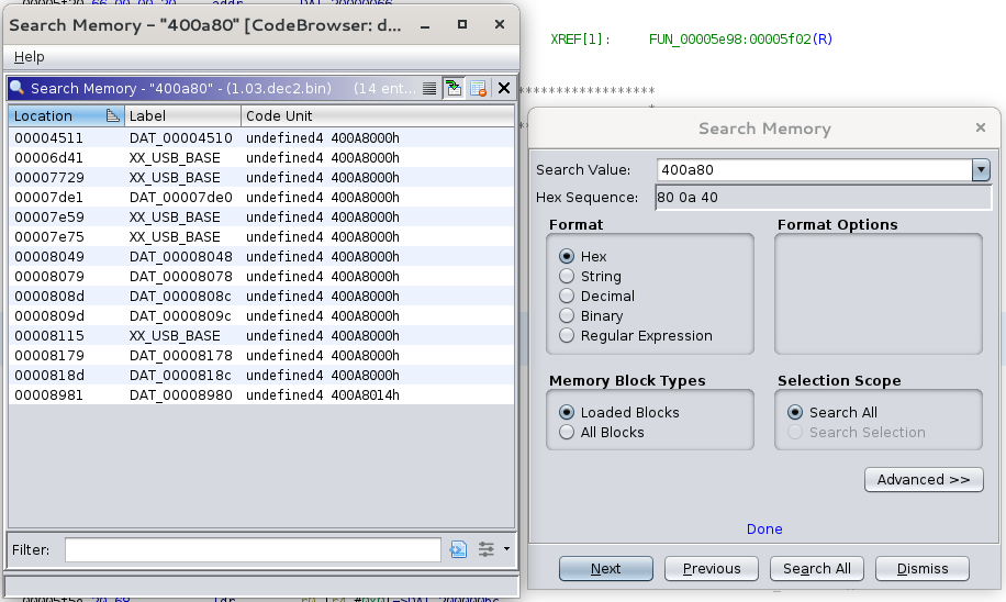
Working by hand, we can look in the datasheet to find that the base address of
the USB peripheral is 0x400A8000, then we can search in Ghidra for any memory
locations containing 0x400A80 and hopefully that will find us code which
interacts with the USB peripheral (I’ve already labelled a bunch of them in
this screenshot):
Working through the disassembled and decompiled code is pretty tough, but it turns out that much of it uses Holtek’s libraries, which we can get the source code for from their website. Using this source code, we can compare it to the decompiled code side-by-side and it helps a lot with figuring out what bits of the code do.
After spending a few evenings working through the firmware, I was quite confident about a couple of things:
- There’s no flash programming routines in the code in the updater
- There’s no CRC checking or blob decoding in the code from the updater
A brief detour into physical access
Throughout this whole thing, I’ve been trying to avoid physically soldering to the keyboard. However, failing to find what I wanted in the firmware blob, I thought I would at least try.
Taking the keyboard apart and probing around I was pretty pleased to find that the board actually has a 5-pin 0.1" header footprint, which breaks out the SWD debug pins and sits right under the space bar! This means you can solder a header onto it, and leave that in place without needing to modify the case or otherwise interfere with the operation of the keyboard!
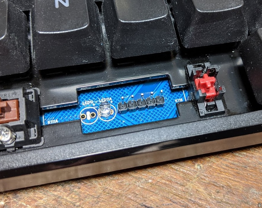
The pinout is:
 |_|  o  o  o  o
  |   |  |  |  `--- GND
  |   |  |  `------ nRST
  |   |  `--------- SWCLK
  |   `------------ SWDIO
  `---------------- 3v3
I soldered a header on, and used openocd on a Pi Zero in USB gadget mode to
see if I could learn anything that way. I knew this was unlikely, due to the
flash protection features of the microcontroller. If activated, this prevents
any access to flash on the CPU’s data bus when a debugger is attached, which
prevents the debugger from reading out the flash contents, but also prevents
the code on the keyboard from reading flash, which crashes it pretty quickly.
I was able to hand-write some machine code into RAM and jump to it, but as suspected, I couldn’t read any flash locations that way (though I could dump peripheral registers, not terribly useful).
Still, hopefully in the future I’ll be able to dump the whole of flash, then mass-erase it to remove the flash protection, and then the SWD header will be very useful for debugging and developing new firmware.
Attempting to modify the firmware
Without a full flash dump to restore from, I was really hesitant to attempt to modify the firmware, as it risks bricking the keyboard with no way to restore working code. However, seeing that the IAP code wasn’t in the blob from updater, I was fairly confident that it was in another part of flash which is protected from accidental breakage.
So, I made the smallest modification I could: In the product name string
“USB-HID Keyboard”, I changed “HID” to “KID”, re-encoded the data, dumped it
back into the right part of the .exe file, copied it over to Windows and ran
it.
It ran as usual, and let me start the programming process - but then at the part where it normally resets back into “normal” operation mode, the keyboard LEDs stayed off and after around 10 seconds of waiting the updater said “Firmware Update Failed!”.
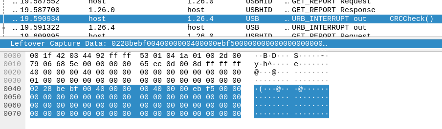
I was capturing the data with Wireshark, and could see that only my single byte
was actually changed in the programming sequence - so my modification of the
.exe was successful, it just didn’t work on the keyboard.
Thankfully, running the non-modified updater, it was able to put “good” firmware back on, and I knew that I could be a bit more confident about hacking around because it seemed like I’d be able to recover with the original updater.
But why didn’t it work? After some more investigation, I found that the final
operation, which writes the version string (V2.1.03) to address 0x3c00
didn’t work, and that memory was still erased (erased in flash memory means
full of 0xff values - programming flash can only clear bits, so to set them
it has to be erased to 0xff). I’ve no way to tell if the rest of flash was
successfully written, but one of my theories is that if the version string
isn’t programmed, the keyboard doesn’t jump from the “IAP” code to the
“Keyboard” code.
The key seems to be the ISP_CRCCheck() function, which runs after all of the
firmware data is sent, but before the version is written. This takes a 16-bit
value from one of the updater structures, and sends it with command type 02.
This must represent some kind of CRC of the data, and with my modification of the firmware I made the CRC invalid. This either prevents any flash programming, or prevents the version string from being programmed.
Trying to figure out the CRC
I haven’t found out how the CRC is calculated yet. It isn’t a simple CRC of the
firmware data (either encoded with the 52-byte key or not). There’s a tool
called reveng which Hackaday did a nice
write-up
on
which can be used to reverse-engineer CRCs, but giving it the three firmware
versions I have didn’t give me any usable results.
What I do know is (from later experiments):
- Just skipping the CRC check doesn’t work
- Appending a zero byte to the firmware doesn’t work
- Changing the CRC value breaks it
- Writing only part of the firmware breaks it
- Re-ordering the firmware writing (e.g. writing the second half first) breaks it
- Putting other operations (like a read) in the middle of the firmware write is OK
- Changing the packet transfer length breaks it
- Simply erasing and re-writing the version, with no other changes, doesn’t work
I intend to keep using these clues to work at figuring out the CRC, then I should be able to modify the firmware in order to read out the contents of flash.
Succeeding and failing
Unable to modify the firmware, I took my various hacked up scripts and wrote a much better/neater tool and couple of libraries, which I’ve uploaded to github:
https://github.com/usedbytes/ducky-tools/
Armed with this, and an updater .exe from Ducky, it should be possible to
update the keyboard firmware on Linux or any other operating system supporting
go (and libusb). So that’s a success I guess? I’ve tested this on my
UK-layout (I don’t know why the updater says ANSI not ISO) Ducky One TKL, with
v1.03r firmware. I don’t know it if works beyond that, but I think if
modifications are needed they should be pretty minor. If you do happen to try
it, let me know how it goes on GitHub, I’m happy to accept improvements or make
changes myself.
$ sudo ./ducky iap update ../One_TKL_EU_L_1.03r.exe
Firmware version: V2.1.03
Name:             KB Upgrade
IAP version:      v1.0.0
Layout:           ANSI 108 Keys
File Key:         ea 61 87 ed
Device Info:
Chip:         HT32F1654
Option Size:  0x0400 (1024)
Flash Size:   0x0000c000 (49152)
OB_PP Bits:   0x0030 (48)
Start Addr:   0x00004000
Version Addr: 0x00003c00

Device Version: V2.1.03
>>> Erase version...
>>> Erase program...
>>> Write program...
>>> Check CRC...
>>> Write version...
>>> Success!
However, through all of this there’s been an implicit goal that just updating with the factory firmware isn’t nearly as interesting as updating with our own code. There are already keyboard firmware projects, and it’s definitely possible to flash them by totally erasing the chip and starting from a clean slate. However, what I really want to do is get a full backup of the stock firmware as a starting point. This would then allow us to keep the stock IAP code, and allow us to switch back to Ducky’s firmware with their official updater.
So, I’m going to keep plugging at the CRCCheck(), and maybe I’ll start taking
a look at my Ducky One2 keyboard, too!