Reverse Engineering keyboard firmware with Ghidra - Part 4 (Conclusion)
This post has been a bit delayed for noe reason in particular (except perhaps fatigue with the project). It brings the Ducky reverse engineering adventure (mainly) to a close.
At the end of Part 3, all of the pieces were in place, but I still wasn’t able to flash my own modified firmware to the keyboard because of a pesky failing CRC check.
What I did know, was that after sending the CRCCheck() command, the keyboard
responded with a 16-bit value.
Dumping memory one-byte at a time
The function signature for ISP_CRCCheck() in the Holtek documentation didn’t
match what I saw in the code, as it had the mysterious 3rd argument (the check
value for the firmware blob, which was required for the download to work).
Looking at the different traffic captures I had, and testing a few different argument values, I suspected the function pseudo-signature was:
/*
 * Sends the 'check' value for download verification, and calculates and
 * returns the CRC value for 'length' bytes starting at 'addr'
 */
uint16_t ISPCRCCheck(uint32_t addr, uint32_t length, uint16_t check);
I tried to confirm this by setting addr and length to areas of flash which
I knew the contents of (because I have the firmware blob), but this was
hindered because the IAP code erases the flash if check is incorrect,
where “incorrect” is based on rules I didn’t understand.
However, we know the value of erased flash: It’s always 0xFF, so I was able
to somewhat confirm my theory by checking the returned 16-bit value against
CRCs for a series of 0xFF bytes. The rest of the code uses the xmodem CRC
algorithm, and it turns out this is no different. The returned 16-bit value was
matching the xmodem CRC for a string of length 0xFFs.
I tested a few “low” addresses (below 0x4000 where the firmware starts), and
got back different values… and so then I had a cunning plan.
I can ask for the CRC of a single byte, which will return me a 16-bit CRC value. This value will be unique for each different input byte value - which means I can back-calculate the input byte value from the CRC value using a look-up table.
By requesting the CRC for every byte in memory, I can dump the values in flash:
// First make a lookup table for all the CRC values
crct := crc16.MakeTable(crc16.CRC16_XMODEM)
lu := make(map[uint16]byte)
for i := 0; i < 256; i++ {
	crc := crc16.Checksum([]byte{byte(i)}, crct)
	lu[crc] = byte(i)
}

dump := make([]byte, 0x4000)

start := 0
end := 0x4000

// Ask for a CRC of one byte of flash
for addr := start; addr < end; addr++ {
	xcrc, err := iapCtx.CRCCheck(uint32(addr), 1, 0)
	if err != nil {
		return err
	}

	// Look-up the CRC value in the table to get the byte value
	val := lu[xcrc]

	dump = append(dump, val)
}
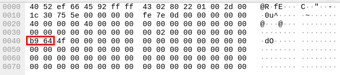
A short while later, I had a reasonable-lookup flash dump! Reasonable because
because at address 0 was 0x20000f58, which certainly looks like a stack
pointer!
The process was a little slow, because I wasn’t providing the correct check
value, meaning that after every CRCCheck() command it was erasing the whole
firmware flash region.
Finally, reverse-engineering the IAP code
Now that I finally had a full dump of the start of flash, I could start reverse engineering the IAP code itself.
The code is pretty similar to the “normal” keyboard firmware which I was pretty familiar with by this point, and that made my work a little faster. I also tracked down the correct SVD file for my chip and used Thomas Roth’s (@StackSmashing) SVD loader tool to automatically annotate all the peripheral addresses, which was really helpful.
After some time, I’d determined how the download and CRCCheck() code worked:
Basically the IAP code has an internal CRC value which is updated in two ways:
- On each invocation of
WriteData(..., data):crc = XModemCRC(crc, XORDecode(data)) - On each invocation of
CRCCheck():crc = XModemCRC(crc, [0x01, 0x23, 0x45, 0x67, 0x89, 0xAB, 0xCD, 0xEF])
This secret extra data used in CRCCheck() was the last missing piece of the
puzzle: [0x01, 0x23, 0x45, 0x67, 0x89, 0xAB, 0xCD, 0xEF], and the only way
to find it was dumping the IAP code out of flash.
Knowing this, it was straightforward to update my code to:
- Be able to dump flash via CheckCRC without erasing flash after every byte (because I know how to generate a correct
checkvalue) - Flash my own modified firmwmare - again because I now know how to generate the correct
checkvalue.
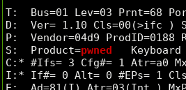
So, now the keyboard is officially pwned - as evidenced by changing the USB product string:
One more thing that might be of interest to anyone still reading is how the keyboard’s boot sequence looks:
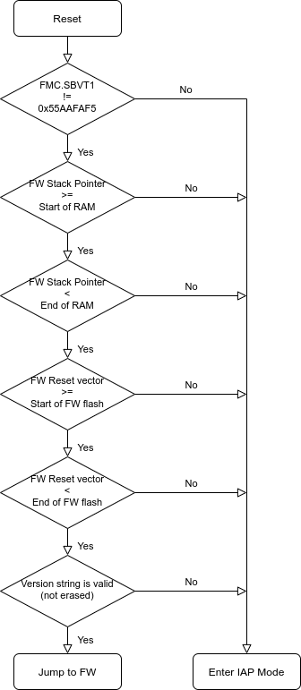
There’s a sequence of checks which try to ensure that the firmware is valid before the IAP bootloader jumps to it, and if any of them fail then the keyboard enters IAP mode. This helps to make it very hard to brick the keyboard, because a lot of things need to go right for it to exit IAP mode. This means that the chances are if something goes wrong during an update, the worst that happens is it gets stuck in firmware update mode, and can still be re-flashed. Good job Ducky!
The first check - FMC.SBVT1 != 0x55AAFAF5 allows the “normal” keyboard
firmware to enter IAP mode by setting that register before triggering a reset.
The FMC registers persist over a soft reset, so this is used to tell the
bootloader that the firmware wanted to enter IAP mode.
One more thing: Nuke it from orbit
There was still one thing bothering me - the pesky copy and debug protections enabled on the chip, which prevent reading flash and debugging via SWD.
The only way to clear these protections is to “Mass Erase” the chip - which wipes absolutely everything, including the IAP code and the copy protection. Without having a copy of the IAP code, I was obviously hesitant to do this, but now I have a copy I can completely wipe the chip and then restore it from my backup.
I double- and triple-checked my backups to be sure I could restore the
keyboard, and then used openocd1 and the SWD header under the spacebar to
nuke everything, and then restore it without copy/debug protection. I did
turn erase protection back on for the IAP bootloader pages, just so I can’t
accidentally erase them with my buggy code.
So now I have a keyboard which acts as stock, and can be updated using stock firmware images - but also be debugged via SWD, and flashed with my own code at my leisure.
Wrapping up
All of my work so far is wrapped up neatly in my ducky-tools
repository, which can dump flash via
the CheckCRC() method, and program new modified or unmodified firmware on
(theoretically) any platform which can run golang and gousb.
From getting a .exe from the Ducky website, to modifying the firmware and
flashing it back, the sequence looks like this:
# First, extract the 52-byte XOR key, to allow us to get descrambled firmware
./ducky extractkey -o out.key One_TKL_EU_L_1.03r.exe

# Then extract and descramble the firmware
./ducky extract -o out.toml One_TKL_EU_L_1.03r.exe

# Now modify `out.toml` and remove the `check_crc` line. Modifying the firmware
# will invalidate this, so we must remove it to have it calculated automatically
sed -i '/check_crc/d' out.toml

# Make whatever modifications you want to the firmware (internal.plain.bin file)

# Re-flash the modified firmware
./ducky iap update out.toml
Someday in the future I’d like to put some custom firmware on the keyboard - perhaps port QMK to it, but for now I’ve sunk enough time into this project, and I’ve achieved my original goals of developing a firmware updater for Linux and learning how to use Ghidra, so for now, I’m calling this project “done”.
-
Upstream
openocddoesn’t support flash commands on the HT32F1654, so I used Charlie Waters' fork on GitHub ↩︎