M5Stack Core2 early impressions
Initial impressions of the M5Stack Core2
Just after Christmas I ordered an M5Stack Core2 (referred to as M5Core2 in many places) on a bit of a whim. I’ve been annoyed about my lack of a self-contained rapid-prototyping platform, and the M5 hardware looks pretty good, and appears popular online.
Historically I’ve used original Mbed LPC1768 boards which I’ve collected over
time. However the “old” online compiler platform for Mbed is more-or-less
unsupported now, and last time I tried the newer mbed-cli system, I had a lot
of trouble setting it up.
I was pretty impressed with my first foray into using the ESP32, and the M5Core2 uses the same PMIC chip as the T-Beam board. With that, the built-in battery, small form factor, and touch-screen input, I figured it would make a good addition to my workbench, so I ordered one for around £30 delivered from Banggood (on one of their frequent “special offers”).
Summary
If you just want a quick run-down of my first impressions after a week of evenings playing with the M5Core2, here they are:
- Overall, it’s a nice board. The features are good, and I can see myself using it a lot.
- The “unboxing” experience is great. The demo app works well, and the general feel of the packaging and device is great.
- The hardware is really nice, but with a few notable kinks.
- At the time of writing, the available documentation is a bit sparse
- Arduino on an x86 machine is the most-supported workflow, which is fine - but it’s very difficult to use anything else due to missing documentation and key files.
If you’re looking for a simple, plain ‘C’, ESP-IDF example (which I couldn’t find at all), then you can see my project on github: https://github.com/usedbytes/m5core2-basic-idf/
Unboxing and Demo
The packaging that the M5Core2 comes in is really nice. It would make a fine long-term storage box for it, though the only thing that secures the inner cardboard box to the outer sleeve is a sticker which will soon run out of “stickiness”.
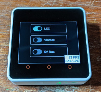
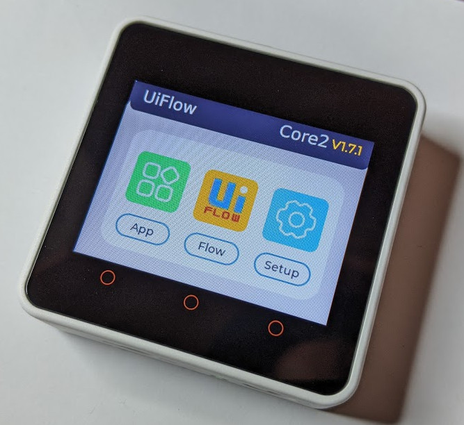
On first power on, it will start up a shiny GUI test application, which tests the various components and just generally shows off the device.
In my estimation, the M5Stack team spent a lot of their software development time on this demo, to ensure that customers got a nice first impression. It works well - I immediately tweeted that I was impressed - but I had quite a frustrating time trying to flash my own stuff.
New toy from @m5s, impressive out-of-box experience #M5Stack pic.twitter.com/KS7oEDg0en
— Brian Starkey (@usedbytes) January 11, 2021
From a business perspective I guess it makes sense - a lot of coverage nowadays is from YouTubers or bloggers who will only have time to unbox the thing and turn it on, so making it look good to them generates good PR. And let’s be realistic, I expect many of us buy a gadget like this, turn it on to see that it works, then put it straight in a drawer for “later use”, so if the first thing we see is flashy, we’re happy.
Hardware
The hardware is good. The case is solid, the selection of peripherals is decent, and they’ve packed most of the stuff you’d want in a “core” module right into the package, so from that perspective I’m pretty happy. The accelerometer and microphone are on the expansion board, which is fine really, but I will probably not keep that installed most of the time. Also, the schematics are available, which is fantastic.
There’s a few parts of the electronic design that I’m not so happy with, especially as this device is marketed for use as a low-power IoT device.
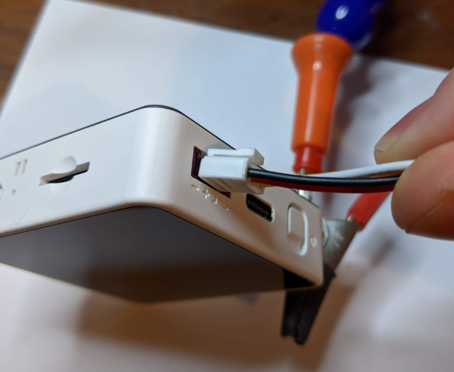
The M5Core2 has 6 different power domains, and 3 different power sources. The PMIC can switch between the different sources seamlessly, which are:
- 390 mAh lithium polymer battery (single cell, 3.7 V)
- USB-C input (5 V only, presumably)
- External 5 V power
The external 5 V power is interesting, because it’s both an input and an output. In “input” mode, the PMIC can take 5 V from the header pin, and use it to power the board and (I think) charge the battery. However, so that there’s also 5 V available for the Grove connector and the “BUS” when running on battery power, there’s also a boost converter on the board, which can boost the battery voltage to 5 V.
To choose between those two modes, you need to set AXP_GPIO0 appropriately.
For internally generated 5 V, AXP_GPIO0 needs to be high, which drives
N_VBUSEN telling the PMIC to ignore the 5 V input, then you can safely enable
EXTEN to turn on the boost converter. For externally-supplied 5 V, EXTEN
needs to be disabled to turn off the boost converter, and N_VBUSEN should be
low, so that the external 5 V can be used as the main power source.
Note that this is all separate from the USB input - USB power will work as you would expect, without any tweaking or tricks.
For the AXP192, N_VBUSEN seems to be designed for devices with “USB OTG”
functionality, where you might want to use USB power as an input (for charging)
but also as an output (for driving a USB device).
This is a neat feature! So far I haven’t used the 5 V bus input, but anyone
programming the M5Core2 will need to take care to set N_VBUSEN before turning
on the 5 V boost converter.
The power domains are:
MCU_VDD: Driven byDCDC1, adjustable (3.3 V)- Turned on by default at boot
- Drives:
- ESP32
- Flash
- PSRAM
- Touchscreen
- Pull-ups on both i2c buses
- Speaker amp
- Power LED
- BUS 3.3V
LCD_BL: Driven byDCDC3, adjustable (2.8 V)- Drives:
- LCD Backlight
- Drives:
RTC_VDD: Driven byLDO1, fixed (3.3 V), always on- Drives:
- The on-board RTC
- Not the ESP32 RTC
- Drives:
PERI_VDD: Driven byLDO2, adjustable (3.3 V)- Drives:
- SD Card slot
- LCD driver logic
- Drives:
VIB_MOTOR: Driven byLDO3, adjustable (2.8 V)- Drives:
- Vibration motor
- Drives:
BUS_5V: Driven byEXTEN+ boost converter (5 V), or externally- Drives:
- 5 V on BUS
- 5 V on Grove
- Drives:
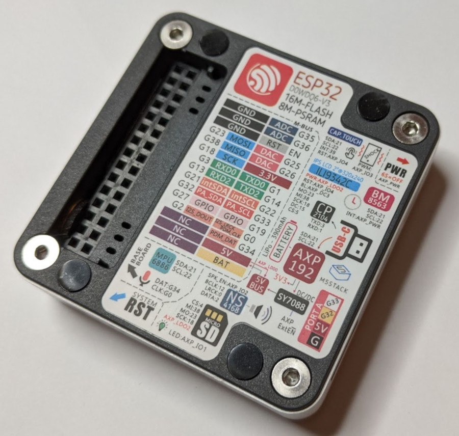
Wow that’s a lot of stuff! There’s a huge amount of control and configurability here. There’s a handy cheat-sheet on the back of the device.
I’m a bit surprised about the number of things in the MCU_VDD domain, as these
are all things which you’re “paying for” during ESP32 deep sleep - which should
be a key feature for anyone working on IoT things. In particular, I don’t feel
the speaker amp and touch screen should have been put in MCU_VDD.
Using a whole separate rail for both the vibration motor, and another for the
backlight, also seems rather wasteful. Both of those could have been driven with
simple transistors sharing a single supply, freeing one up to split MCU_VDD.
Having the RTC on a separate voltage rail (LDO1 is specifically designed
for this purpose) is nice. The RTC “alarm” pin is wired to the AXP192 power key
input, so it should be possible to completely “power off” everything except the
RTC, then use the RTC alarm functionality to turn back on.
What I can’t figure out is why (according to the schematic) the AXP192 IRQ pin isn’t wired to the ESP32. This would allow the application to get interrupts on various PMIC events, like power connected, button pressed, RTC alarm. Without this, the app needs to poll the AXP192. I plan to look at soldering a wire on here, to hook up the IRQ.
The last strange thing I’ve noticed about the hardware is the Grove connector. I bought “Seeed Grove” cables from Rapid (via ebay), and was surprised to find they don’t fit! The cables have a clip, which doesn’t fit into the slot on the M5Core2. It’s trivial to snip the clip off, and then it works fine. But I was surprised to find that it wasn’t compatible out-of-the-bag.
Arduino
As far as I can see, Arduino is the way this board is “meant” to be used. The first thing I wanted to do was try and re-build the factory demo application so that I could put it back to it’s “default” state, before I started breaking things with my code.
I’ve never been an Arduino person, but presumably this process is familiar to those that are proficient with the Arduino environment setup. To use the M5Core2 you need to:
- Add the ESP32 boards via the Board Manager
- Board Manager requires an Arduino IDE version 1.8 or greater, which is newer than the one in the Raspbian repositories, so you may need to download it from arduino.cc directly.
- Add the M5Core2 library
- Get the example project(s)
- The Core2 factory example is Core/M5Core2/Arduino/Core2_Factory_test/Core2_Factory_test.ino
This does work, and I did manage to build and run it - but I had quite a few issues along the way because I’m on a Raspberry Pi 4 running 64-bit Raspbian.
The arduino-esp32 page says:
We have packages available for Windows, Mac OS, and Linux (x86, amd64, armhf and arm64).
So I assumed my linux-arm64 machine would be OK, but the board support
wouldn’t install, saying that some of the tools aren’t available for linux-arm64.
I did pull the code directly into ~/Arduino, and hooked up the tools
from my existing ESP-IDF installation, but then I ran into compilation issues.
It turns out that the arduino-esp code is built against ESP-IDF v3.x, and my
installation is v4.2. Amongst other things, the compiler version in 3.x is gcc5.2, and in 4.2 it’s gcc8.2,
so the build wouldn’t work and I had to obtain an older compiler. I didn’t find
a binary linux-arm64 package I could use, but I’m familiar with crosstool-ng
so I just built the correct toolchain from scratch.
Oh, and naturally ESP-IDF v3 is using Python 2.7, and v4.2 uses Python 3, so
there’s update-alternatives
“fun” in here too.
I understand that I’m running on an unsupported platform, but my main gripe
with this process is that nowhere on the arduino-esp page does it say what
ESP-IDF or compiler version it needs. There’s a link at the bottom of the
“use as a component for ESP-IDF page”,
to a vaguely related issue,
where the recommendation seems to be “check the git log for a commit which
updates the ESP-IDF version, and use the same commit”, but this is just awful
developer experience.
To be clear though: arduino-esp32 is an Espressif project, and so this isn’t
directly related to M5Stack, just to ESP32 Arduino development in general.
M5Stack UIFlow
One of the more attractive features of the M5 line is their UIFlow online blocks + python IDE.
This lets you write programs with scratch-like Blockly blocks, which are backed by MicroPython code underneath - so you can switch back and forth. M5Stack provide a firmware image which can connect to their cloud system, so you can build your programs right in the browser and deploy over WiFi to your board.
From a usability standpoint, this is perfect for the kind of quick on-bench prototyping I want to use the M5Core2 for - in theory.
Getting set up is documented under UIFlow Quick Start, where the curse of the unsupported platform struck again. The only place you can get the firmware for M5Core2 (as far as I can tell) is via the M5Burner tool, which is only available for x86 and so won’t run on my Pi.
M5Burner is a sort of “app store” for M5Stack, where you can download various different programs from M5Stack themselves, or the community. However, being x86 only, if you’re on a Pi like me, it’s all totally inaccessible (as far as I can tell).
In principle, I don’t have a problem with M5Stack providing this burner tool, and only supporting certain platforms with it. But at the very least, they need to provide a direct link to the firmware file so that people can flash it directly if they don’t want, or can’t use M5Burner.
For other boards (M5Core v1, M5Stick etc), I think the firmware binary at https://github.com/m5stack/UIFlow-Code/tree/master/firmware would work, but it doesn’t for M5Core2.
So, I booted an x86 machine, installed M5Burner, and got the firmware.
Thankfully it just gets dropped in a directory on disk, so I can copy it back
to my Pi and flash it with esptool directly.
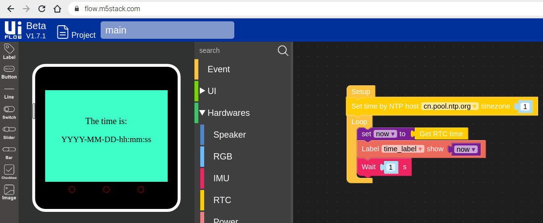
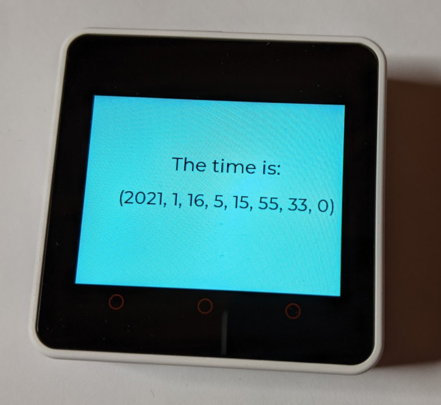
Once that firmware is loaded, the flow from browser to board works well, and it’s trivial to set up a little UI application:
I haven’t had any luck running python programs from the menu on the M5Core2 itself, they just hang as soon as you press “run”, but from the web, or automatically on boot, it works fine.
The web UI is OK, but switching between Python and Blockly doesn’t work well, and your Python changes are easily lost with a few mis-clicks. It definitely needs some better file management.
The other deal breaker for me, is that the Python API is effectively undocumented, and the source code isn’t available - so there’s no way for anyone to improve it. Also this means that if the functionality you want isn’t there, you’re going to have a hard time adding it.
It looks like an older version of the MicroPython libraries are available in that repo, but it doesn’t have anywhere near the full set from the Web IDE, and doesn’t support M5Core2.
There is some kind of offline IDE available, but with that you can’t upload the code over WiFi, so it loses a lot of its appeal.
This system is so close to being incredible! But for me to use it in earnest, I would want:
- WiFi download over local network, with locally-hosted server
- Offline IDE with no cloud dependency (or even better, just let me use my text editor directly)
- Full python library source code (or at least documentation!)
ESP-IDF
Given that ESP-IDF is the “main” development environment from Espressif for working with ESP32, I’m very surprised that M5Stack don’t mention it at all on their site, and don’t provide any documentation or examples that I could find to work with it.
In any case, it wasn’t too difficult to set up a basic ESP-IDF based project using LVGL to provide the UI and touch-screen support (which I think is the same underlying system as UIFlow and the factory example uses).
I’ve uploaded my project to github. I’d say just see the README there if you’re interested, I won’t duplicate it here.
It was relatively painless, with just a couple of library quirks to work-around.
It’s worth saying that I’m quite impressed with LVGL. It’s very featureful and
easy to use. The lvgl_esp32_drivers repo is a bit more of a mess, but the core
graphics library seems pretty solid.
Conclusion
All in all, now I’ve learnt all the things I’ve written about here, I’m quite happy with this platform. I’m sure M5Stack will continue to improve the software, as this board is only around 6 months old. I look forward to using this thing in practice on my bench!