ESP32 WiFi/Bluetooth Bridge
ESP32-based WiFi and Bluetooth bridge for M0o+
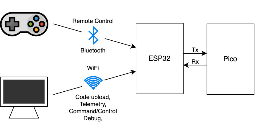
M0o+ is my Raspberry Pi Pico-based robot entry for Pi Wars at Home 2022.
A Pi Wars robot needs to be remote-controllable, and network connectivity is extremely useful for telemetry, debugging etc. As the Pico doesn’t natively have any kind of wireless connectivity, I’m using an ESP32 to provide that functionality. It connects to a bluetooth gamepad, relaying controller input to the Pico, and acts as a WiFi access point to provide network connectivity.
The only link between the ESP32 and the Pico is a single UART, and the controller/network data is multiplexed onto that single shared connection.
WiFi
The ESP32 SDK makes the WiFi part of the equation quite straightforward. I started with the sofAP example and use the standard BSD sockets API to expose a TCP server.
The details of the serial multiplexing I’ll go into more below.
I’ve set it up so that the ESP32 will only accept WiFi connections from a single device at a time, so that there can be no confusion, and it will also only accept a single socket connection at a time.
Initially I didn’t have the Bluetooth gamepad part implemented, so no multiplexing was necessary, and I simply had a loop which read data from the socket and sent it to the UART, and read any data from the UART and sent it to the socket.
Right now, the ESP32 is running as an access point, I haven’t implemented connecting to an existing network. That means that the computer has to connect directly to the ESP32, and so can’t use the same WiFi card to connect to the internet simultaneously. My development machine (a Raspberry Pi 4) connects to the internet over ethernet, so it hasn’t been a problem so far to dedicate the WiFi connection to the ESP32.
Bluetooth
This is my first time trying to implement anything using Bluetooth. Unlike BSD sockets for TCP/IP, there’s no standard abstraction for Bluetooth so the BT side of the equation is more complex than WiFi.
The gamepad/controller I’m using is an 8bitDo SN30 Pro which is nominally for the Nintendo Switch, but it also supports the standard Bluetooth HID profile, which makes it quite easy to connect to other things.
Searching around, I found the btstack Bluetooth stack
which has support for the ESP32, and an example of being a HID Host1.
Getting up and running with the SN30 Pro and the btstack example was quite
easy, but I had to force it to use HID_PROTOCOL_MODE_REPORT rather than
HID_PROTOCOL_MODE_REPORT_WITH_FALLBACK_TO_BOOT.
static hid_protocol_mode_t hid_host_report_mode = HID_PROTOCOL_MODE_REPORT;
The btstack example is designed for a Bluetooth keyboard, which means the
HID reports it expects don’t match the ones put out by the gamepad.
I’m not interested in supporting any and all gamepads,
so I simply printed out the reports which the SN30 Pro was putting out and hard-coded a mapping.
The meaning of the different “Usage Page” and “Usage” values is documented in the HID Usage Tables specification, but it’s not so important. I just pressed each button in turn and wrote down what changed in the values coming from the controller.
The code to decode and handle the reports is below. Notably, the controller sends a few values which don’t correspond to any button, and the “Star” button doesn’t seem to be reported at all.
/*
 * Usage page: 0x1, 0x39, 0xf       HAT
 * Usage page: 0x1, 0x30, 0x80      X (Lx)
 * Usage page: 0x1, 0x31, 0x80      Y (Ly)
 * Usage page: 0x1, 0x32, 0x80      Z (Rx)
 * Usage page: 0x1, 0x35, 0x80      Rz (Ry)
 * Usage page: 0x2, 0xc4, 0x0       Accelerator (R2)
 * Usage page: 0x2, 0xc5, 0x0       Brake (L2)
 * Usage page: 0x9, 0x1, 0x0        A (Circle)
 * Usage page: 0x9, 0x2, 0x0        B (Cross)
 * Usage page: 0x9, 0x3, 0x0
 * Usage page: 0x9, 0x4, 0x0        X (Triangle)
 * Usage page: 0x9, 0x5, 0x0        Y (Square)
 * Usage page: 0x9, 0x6, 0x0
 * Usage page: 0x9, 0x7, 0x0        L1
 * Usage page: 0x9, 0x8, 0x0        R1
 * Usage page: 0x9, 0x9, 0x0
 * Usage page: 0x9, 0xa, 0x0
 * Usage page: 0x9, 0xb, 0x0        Select
 * Usage page: 0x9, 0xc, 0x0        Start
 * Usage page: 0x9, 0xd, 0x0        Heart
 * Usage page: 0x9, 0xe, 0x0        L3
 * Usage page: 0x9, 0xf, 0x0        R3
 * Usage page: 0x9, 0x10, 0x0
*/
#define USAGE_PAGE_DESKTOP  0x1
#define USAGE_PAGE_SIM      0x2
#define USAGE_PAGE_BUTTON   0x9

#define DESKTOP_USAGE_HAT 0x39
#define DESKTOP_USAGE_LX  0x30
#define DESKTOP_USAGE_LY  0x31
#define DESKTOP_USAGE_RX  0x32
#define DESKTOP_USAGE_RY  0x35
#define SIM_USAGE_R2      0xc4
#define SIM_USAGE_L2      0xc5

#define BTN_BIT_A       0
#define BTN_BIT_B       1
#define BTN_BIT_X       2
#define BTN_BIT_Y       3
#define BTN_BIT_L1      4
#define BTN_BIT_L2      5
#define BTN_BIT_L3      6
#define BTN_BIT_R1      7
#define BTN_BIT_R2      8
#define BTN_BIT_R3      9
#define BTN_BIT_START   10
#define BTN_BIT_SELECT  11
#define BTN_BIT_HEART   12
#define BTN_BIT_STAR    13

struct bt_hid_state {
	uint16_t buttons;
	uint8_t lx;
	uint8_t ly;
	uint8_t rx;
	uint8_t ry;
	uint8_t hat;
	uint8_t pad;
};

static void hid_host_handle_interrupt_report(const uint8_t * report, uint16_t report_len){
	// check if HID Input Report
	if (report_len < 1) {
		return;
	}

	if (*report != 0xa1) {
		return;
	}

	report++;
	report_len--;

	btstack_hid_parser_t parser;
	btstack_hid_parser_init(&parser,
			hid_descriptor_storage_get_descriptor_data(hid_host_cid),
			hid_descriptor_storage_get_descriptor_len(hid_host_cid),
			HID_REPORT_TYPE_INPUT, report, report_len);

	struct bt_hid_state state = { 0 };

	while (btstack_hid_parser_has_more(&parser)){
		uint16_t usage_page;
		uint16_t usage;
		int32_t  value;
		btstack_hid_parser_get_field(&parser, &usage_page, &usage, &value);

		//printf("Page: 0x%x, Usage: 0x%x, Value: 0x%x\n", usage_page, usage, value);

		switch (usage_page) {
		case USAGE_PAGE_DESKTOP:
			switch (usage) {
			case DESKTOP_USAGE_HAT:
				state.hat = value;
				break;
			case DESKTOP_USAGE_LX:
				state.lx = value;
				break;
			case DESKTOP_USAGE_LY:
				state.ly = value;
				break;
			case DESKTOP_USAGE_RX:
				state.rx = value;
				break;
			case DESKTOP_USAGE_RY:
				state.ry = value;
				break;
			}
			break;
		case USAGE_PAGE_SIM:
			switch (usage) {
			case SIM_USAGE_L2:
				state.buttons |= (value ? (1 << BTN_BIT_L2) : 0);
				break;
			case SIM_USAGE_R2:
				state.buttons |= (value ? (1 << BTN_BIT_R2) : 0);
				break;
			}
			break;
		case USAGE_PAGE_BUTTON:
			switch (usage) {
			case 0x1:
				state.buttons |= (value ? (1 << BTN_BIT_A) : 0);
				break;
			case 0x2:
				state.buttons |= (value ? (1 << BTN_BIT_B) : 0);
				break;
			case 0x4:
				state.buttons |= (value ? (1 << BTN_BIT_X) : 0);
				break;
			case 0x5:
				state.buttons |= (value ? (1 << BTN_BIT_Y) : 0);
				break;
			case 0x7:
				state.buttons |= (value ? (1 << BTN_BIT_L1) : 0);
				break;
			case 0x8:
				state.buttons |= (value ? (1 << BTN_BIT_R1) : 0);
				break;
			case 0xb:
				state.buttons |= (value ? (1 << BTN_BIT_SELECT) : 0);
				break;
			case 0xc:
				state.buttons |= (value ? (1 << BTN_BIT_START) : 0);
				break;
			case 0xd:
				state.buttons |= (value ? (1 << BTN_BIT_HEART) : 0);
				break;
			case 0xe:
				state.buttons |= (value ? (1 << BTN_BIT_L3) : 0);
				break;
			case 0xf:
				state.buttons |= (value ? (1 << BTN_BIT_R3) : 0);
				break;
			}
			break;
		}
	}

	xQueueSend(task_params->state_queue, &state, portMAX_DELAY);
}
Serial multiplexing
I need both network traffic and gamepad events to get sent to the Pico over the same UART connection without interfering with each other.
I also want to keep the ESP32 code as simple as possible, and in particular, I want to minimise what it needs to know about the data being sent over the network - because I don’t want to update the ESP32 firmware every time I make a minor change to the robot’s command/control/telemetry.
To satisfy these two requirements, I settled on a “transaction” based system, where the ESP32 is in charge of all serial communication, and it always initiates. The disadvantage of this is that the Pico can’t send data by itself (for example, the robot can’t automatically periodically report its status, it would need to be asked what its status is), but this is an acceptable trade-off for a much simpler “bridge” implementation on the ESP32.
There’s a task in the ESP32 firmware which receives “transaction” objects from a queue. A “transaction” consists of some data to send, an expected response length (how much data do we expect the Pico to send back?) and a callback function which will be called with whatever data is received from the Pico in response.
static void uart_handler_task(void *pvParameters)
{
	txn_event_t txn;
	uart_event_t uart_event;

	for ( ; ; ) {
		// Everything is driven by transactions
		ESP_LOGI(TAG, "Waiting for transaction");
		xQueueReceive(txn_queue, (void *)&txn, portMAX_DELAY);
		ESP_LOGI(TAG, "Transaction: %d bytes (%d)", txn.tx_len, txn.rx_len);

		// Start with an empty RX buffer for every transaction
		// TODO: Is this definitely what we want to do?
		uart_flush_input(UART_NUM);

		uart_tx(txn.tx_data, txn.tx_len);

		uint16_t rx_count = 0;
		bool error = false;

		TickType_t rx_start = xTaskGetTickCount();

		for (rx_count = 0, error = false; rx_count < txn.rx_len && !error ; ) {
			bool timeout = !xQueueReceive(event_queue, (void *)&uart_event, UART_TIMEOUT_MS / portTICK_PERIOD_MS);
			if (timeout) {
				TickType_t now = xTaskGetTickCount();

				uint16_t in_fifo = uart_rx_into(&rx_data[rx_count], txn.rx_len - rx_count);
				rx_count += in_fifo;

				if (in_fifo > 0) {
					// If there was data, wait for longer
					continue;
				} else if (rx_count > 0 || ((now - rx_start) > (UART_TIMEOUT_LONG_MS / portTICK_PERIOD_MS))) {
					// Timeout, send what we have
					ESP_LOGI(TAG, "UART timeout after %d bytes\n", rx_count);
					break;
				}

				// Haven't received any data yet, and the long
				// timeout hasn't been reached. Keep waiting
				continue;
			}

			switch(uart_event.type) {
			case UART_DATA:
				ESP_LOGI(TAG, "UART_DATA %d", uart_event.size);
				ESP_LOGI(TAG, "rx_count: %d, rx_len: %d\n", rx_count, txn.rx_len);
				rx_count += uart_rx_into(&rx_data[rx_count], txn.rx_len - rx_count);
				break;
			case UART_FIFO_OVF:
				// Fallthrough
			case UART_BUFFER_FULL:
				// Fallthrough
			case UART_PARITY_ERR:
				// Fallthrough
			case UART_FRAME_ERR:
				uart_handler_error();
				error = true;
				break;
			case UART_BREAK:
				// TODO: Are we going to use break?
				break;
			default:
				// Unexpected UART type
				break;
			}
		}

		// One last attempt to drain anything in the ring buffer
		rx_count += uart_rx_into(&rx_data[rx_count], txn.rx_len - rx_count);

		ESP_LOGI(TAG, "Calling rx_func %d bytes %d\n", rx_count, error);
		txn.rx_func(txn.priv, rx_data, rx_count, error);
	}

	vTaskDelete(NULL);
}
There are separate tasks for the WiFi socket traffic and the Bluetooth gamepad events which just put “transaction” objects into the queue. Because everything is encapsulated as a request/response pair, the UART gets completely “owned” by each transaction in turn, and there’s never any conflicts between different types of data.
The ESP32 UART code doesn’t know anything about the data inside the transactions, only how many bytes to send, and the maximum number of bytes to receive. For the network traffic, the initiator doesn’t always know what the expected response length is (for example a variable-length logging packet), so the UART code “completes” the transaction whichever occurs first out of:
- Expected number of bytes have been received
- Some bytes have been received, and a timeout occurs
This timeout approach does reduce the maximum throughput, but in my testing so far it hasn’t been a problem.
Serial protocol
The actual data sent over the UART uses the same protocol as I implemented for the bootloader, just with different commands/opcodes.
For the gamepad, there’s a single command which reports the state of all inputs whenever something changes:
#define CMD_INPUT    (('I' << 0) | ('N' << 8) | ('P' << 16) | ('T' << 24))

#define BTN_BIT_A       0
#define BTN_BIT_B       1
#define BTN_BIT_X       2
#define BTN_BIT_Y       3
#define BTN_BIT_L1      4
#define BTN_BIT_L2      5
#define BTN_BIT_L3      6
#define BTN_BIT_R1      7
#define BTN_BIT_R2      8
#define BTN_BIT_R3      9
#define BTN_BIT_START   10
#define BTN_BIT_SELECT  11
#define BTN_BIT_HEART   12
#define BTN_BIT_STAR    13

struct bt_hid_state {
	uint16_t buttons;
	uint8_t lx;
	uint8_t ly;
	uint8_t rx;
	uint8_t ry;
	uint8_t hat;
	uint8_t pad;
};
For the network traffic, there’s a bunch of different commands - which I’ll be extending as I add more functionality.
The neat thing about the ESP32 not knowing anything about the data is that from the host side, I can make the network connection look just like a normal UART and therefore my bootloader and upload code works “out of the box” over the ESP32.
With all that in place, I can upload code over WiFi, receive controller data over Bluetooth, and report those back to a PC over WiFi:
It's taken a lot longer and a lot more effort than I hoped, but everything has finally come together. Flash over WiFi, controller over Bluetooth, telemetry back to the PC over WiFi 🧑💻😌
— Brian Starkey (@usedbytes) October 23, 2021
I might *finally* be able to try some motors tomorrow. #PiWars pic.twitter.com/MmxR44wFqD
Code
I’ll upload the code to Github as with the rest of M0o+’s code, but it looks like I forgot to check in some files, so that will have to wait until I’m back at home after holiday family visiting.
-
I note that ESP-IDF also has a Bluetooth HID host example, using the default ESP32 Bluetooth stack, but for whatever reason I landed at btstack first and that’s what I’ve gone with. ↩︎