M0o+'s Chassis
The chassis design for M0o+
M0o+ is my Raspberry Pi Pico-based robot entry for Pi Wars at Home 2022. This post details what I’ve settled on for the basic chassis of the robot.
Rebound
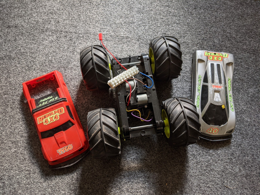
As I wrote in my initial post for the project, I had originally hoped to re-purpose an ancient RC car chassis to be the basis of my robot.
Sadly, it became apparent that all of the things which made it so much fun as an RC car when I was a child, made it almost entirely unsuitable for Pi Wars.
Here follows an over-detailed justification for why…
Batteries
Rebound – which is what the toy was called – ran off 6 V “Jet Turbo!” NiCd batteries, which I must have disposed of in the intervening decades (I hope responsibly! Cadmium is no joke).
A single NiCd cell has a nominal voltage of 1.2 V, which is conveniently the same as the less toxic NiMH cells which replaced them - so it would be perfectly possible to directly replace the 5-cell, 6 V NiCd battery with a NiMH one and get the same voltage (and probably more capacity and current to boot).
Despite NiMH having much higher energy density than NiCd, they don’t pack anywhere near the punch of a modern Lithium Ion (or Lithium Polymer - LiPo) battery. For that reason, I really want to use a lithium battery on M0o+, and therein lies the first problem.
A single lithium ion cell has a nominal voltage of 3.7 V, going up to around 4.2 V when fully charged and down to somewhere around 2.7-3.3 V when discharged depending on the specific cell and chemistry.1
This means that a single lithium cell would be providing significantly less voltage to the motors than the original battery pack, across the whole range of charge levels. Two lithium cells in series would be providing significantly more voltage when fully charged (8.4 V vs 6 V).
In all likelihood, driving the motors from a 2S2 lithium battery would have been fine, but I also found it to be an awkward voltage range to buy a motor driver for: 8.4 V down to 6.6 V doesn’t seem to be a very common operating range, with 8.4 V being higher than “low voltage” drivers' maximums, and 6.6 V being lower than “high voltage” drivers' minimums.
Motors and Gearboxes
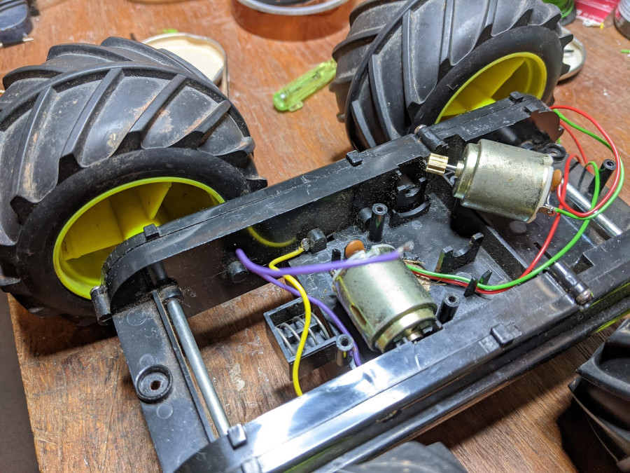
Problem number two was the motors.
The original motors are extremely powerful. I don’t have any real quantitative measure of them, but they draw more than 3 A when stalled at 6 V, which is the maximum my bench supply can manage.
It makes sense, the performance of the RC car was extreme, able to fling itself around and flip over (by design). This vintage advert really isn’t exaggerating:
Initially to get some testing off the ground, I hooked up a puny DRV8837 1.2 A motor driver which I had to hand.3 While it kind-of worked, it was constantly tripping its over-current protection, getting very very hot, and not managing to deliver much power to the motors.
It does the thing!! The poor motor driver is almost constantly in overcurrent shutdown though. Need to go shopping. #PiWars https://t.co/yHTPHPVU28 pic.twitter.com/TB2Fx6tw0y
— Brian Starkey (@usedbytes) October 24, 2021
I did some more testing without a H-bridge, just connecting the motors directly to power, and it was clear that the stock motors were far, far too fast.
PWM control would let me control the speed of the motors somewhat, but Pi Wars needs high precision and relatively low speed; even with PWM it seemed unlikely that I’d get the speed/control that I needed.
The high stall current of the motors was also proving to be quite a problem for motor driver selection, so I started looking for new motors.
The motors themselves are a somewhat standard size: “R260”. Getting some help from the Pi Wars discord, I learnt how to reverse engineer what kind of pinion gear I needed (the key thing being learning about the module number).
I measured the no-load speed of the stock motors with a hacked up optical interrupter circuit and my oscilloscope and found a replacement which claimed to be around half the speed of the stock motors, with much lower stall current. Through much time spent on AliExpress, I also found some pinion gears which were compatible.
To my delight, both the motor and the pinion gear fit, and I was able to swap out the motors.
To my dismay, it became apparent that the gearboxes in the chassis didn’t have a high enough reduction ratio to provide useful torque from the lower power, lower speed motors. The gearboxes are an integral part of the chassis, and there’s really no practical way I could change them.
Simply put, Rebound’s designers made it to be a high-speed, high-power, rock-hopping, jump-making monster, and those design decisions are wholly incompatible with what I need for M0o+.
So with much time wasted, and much stress in having my chassis plan fall apart, I consigned Rebound back to the parts bin.4
New Chassis
I set about designing a new chassis from scratch, and thankfully it went pretty quickly with not too much bother. Working on a much larger robot than Mini Mouse without any awkward size or layout constraints definitely has its advantages.
I picked some 200 RPM, 25 mm motors on eBay, and decided to use the same DBH-12V H-bridge that I used on Bot Matrix.
I bought 4 motors and 2 H-bridges, so that in theory I have independent control of each motor. I won’t use that for M0o+, but maybe I’ll add some omniwheels in the future.
From there, I found out the dimensions of a real JCB telehandler, and scaled it down to fit the Pi Wars size limit (around 1:15).
A bunch of OpenSCAD modelling, 3D printing and laser-cutting later, I had myself a new basic chassis to build on.
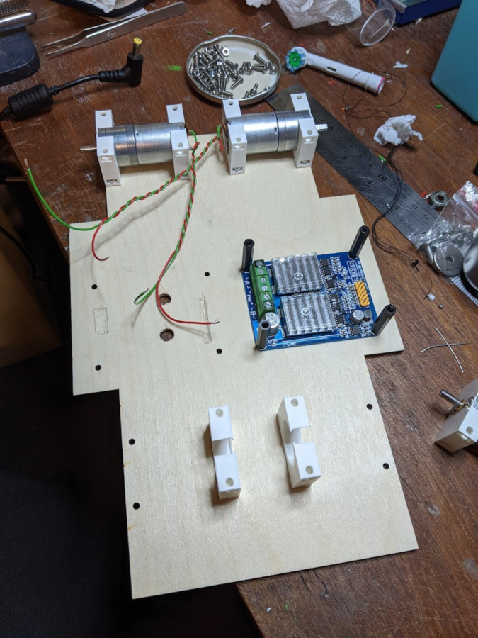
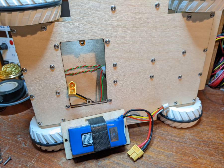
The overall chassis is a sandwich of laser ply with a filling of electronics and motors. The motor mounts are 3D printed, and the plywood bolts into each side with M3 bolts and (sort-of) captive nuts. The H-bridges and power supply circuitry is also in the middle, bolted in and using 25 mm M3 spacers to bridge the gap.
Overall this gives a simple, strong and rigid chassis.
At Robot Club a couple of weeks later I laser-cut a hole in the bottom plate for the battery, and made a little battery door which holds a 3S LiPo and bolts in.
Wheels
For wheels, I spent a very long time looking at various wheels online to try and find something that was the right size and looked the part.
Not able to find anything, I turned to the Pi Wars Discord, and was persuaded that I should just design and 3D print my own wheels.
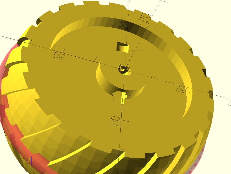
For Mini Mouse I 3D printed wheels, using a silicone O-ring to provide a tyre for grip, and so I actually just took that same design and scaled it up, with a few tweaks to make it more JCB-like. The design was in OpenSCAD and quite parametric, so it didn’t take too much work.
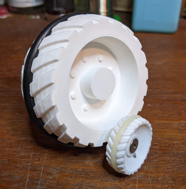
On Mini Mouse I used metal shaft collars to attach the wheels to the shaft with a grub screw, but I couldn’t find any with the right size for my new motors.
Instead, I 3D printed space for a captive M2 nut into the wheel itself, and use a bolt through that to tighten the wheels onto the shafts.
I ordered some suitably large O-rings for tyres, and it all turned out pretty well.
Electronics
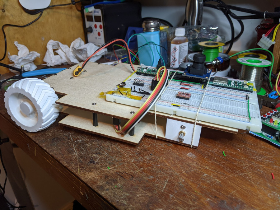
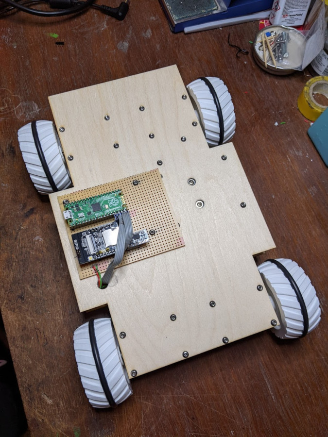
Finally, I needed to get rid of the breadboard which had held my electronics so far.
I ordered a physically smaller ESP32 board (with a camera that I didn’t need)5, and transferred the circuit to stripboard, which bolts on to the top plate using the same holes as one of the H-bridges.
With that all done, I had a new self-contained chassis, all neat and tidy and ready for further development.
-
Also note that a lithium battery’s voltage changes much more than a NiCd battery across its discharge cycle. The original NiCd battery pack would have provided close to 6 V until it was almost entirely empty, whereas a lithium cell drops off much more quickly. ↩︎
-
Two cells in series ↩︎
-
Unfortunately, I used this chassis several years ago a group of A-level students I was mentoring, and I used the original PCB to drive the motors. It didn’t have any kind of protection on the discrete FETs which made up its H-bridges, and so some buggy code turned on both sides of the bridge at the same time. This creates a direct short through the transistors, quickly destroying them, and I must have thrown the circuit board out after that; so I had to find a new motor driver. ↩︎
-
I’d still like to use it - maybe as an outdoor, GPS-guided, much longer-range rover? ↩︎
-
It absolutely boggles my mind that it’s possible to get a dual-core 240 MHz WiFi + Bluetooth processor, with a 2 megapixel camera, from a UK seller, for £6.20 delivered! ↩︎