Motors
Motors were the first thing I worked on selecting at the start of the development process. Given the space constraints I’m working with, motors would be a critical component which would inform the design of the rest of the robot.
Stepper vs Brushed DC
In Bot Matrix I had DC motors with hall-effect encoders on the back. I used the encoders to implement closed-loop control for motor speed, and for odometry for dead reckoning. In my opinion, accurate speed control and odometry are must-have features for a robot - and so this weighs heavily in to the motor selection process.
As with all things, there are tradeoffs for each type of motor - brushed motors tend to be cheap, efficient, fast and powerful. However, they require feedback for accurate control. Stepper motors on the other hand don’t require any feedback (assuming they don’t stall), but require more specialised drivers, and consume far more power.
Brushed DC Motors
Given the space constraints in Mini Mouse, I was reluctant to use encoders, as they would almost certainly require a microcontroller to process. That had me leaning towards stepper motors from the start. However, small steppers do have a lot of limitations, so I did some due diligence looking for DC motors.
The obvious choice is the popular and ubiquitous Micro Metal Gearmotors (MMGM). They’re small, cheap, torquey, and available in a range of different gear ratios. They’re also available with extended shafts and encoders.
Using my CAD model of the mouse, it looked like MMGMs with encoders would be really really tight, back to back, in the chassis. Then in addition, I’d need to fit in either two or four H-Bridges.
There’s some other options for small DC motors with planetary gearboxes, but very few (i.e. none) which ticked the boxes for size, price, performance and - hardest to satisfy - encoders.
Stepper motors
Stepper motors looked appealing, I’d hopefully be able to avoid the need for a microcontroller. There’d be no need for feedback, and I’d hope to drive the motors directly from the Pi.
There’s a variety of tiny stepper motors available - from miniscule 3 mm stepper motors for camera focussing assemblies, up to cheap and ubiquitous 28 mm stepper gearmotors. As you’d expect, such tiny steppers have very low torque, and also relatively large step size - normally 10-20 steps per revolution. For that reason a stepper with a gearbox is effectively essential.
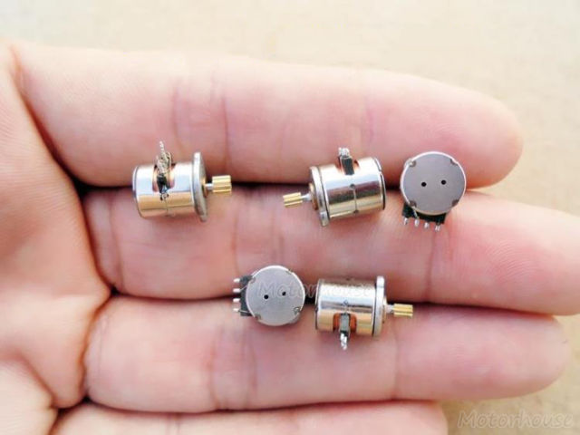
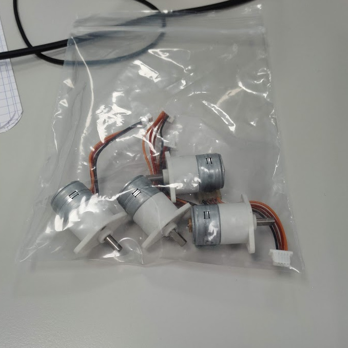
GM15BY
After a great deal of searching, I came across the motors named “GM15-BY”. These are 15 mm stepper motors (usually 20 steps/rev), with a metal gearbox mounted on the front. The gearboxes are actually the same design as used by the Micro Metal Gearmotors.
As far as I can tell, these motors are used in air conditioners - but I’ve no idea what for. Perhaps controlling the vanes? 100:1 seems to be the most common gear ratio for these motors, which is really too high for robot propulsion:
20 steps/revolution * 100 gear ratio = 2000 steps/revolution (output shaft)
At 2000 steps a revolution, we need a step rate of 2000 Hz, just to get 60 RPM. Looking around at the specifications of the motors, it seemed optimistic to get much more than 100 RPM with that gear ratio - so we need something lower.
Various sellers on AliExpress offer a selection of ratios, though normally at around $8 each (and of course with 4 weeks shipping). Thankfully, and quite by chance - I checked eBay one day and there was a brand new listing for a UK supplier of GM15-BY motors, with 30:1 gear ratios, and a price of £3 each, shipped! Bingo, I found my motors.
Motor Driving
Stepper motors are a bit more tricky to drive than DC motors. A bipolar stepper motor has two coils, and turning the motor means energising the coils in a specific sequence, requiring current in both directions through each coil. Effectively, driving one stepper motor requires two full H-bridges and a sequence generator, whereas driving a DC motor only requires a single H-bridge.
Thankfully, stepper motor driver chips exist, which hide away all the details and expose a simple “step + direction” interface. Using just two logic pins, you set a direction and send pulses on the “step” pin to make the motor turn. Even more fortunately, Polulu and the broader RepRap and 3D printer market have led to the creation of the “stepstick” form factor, which means standardised stepper driver breakout boards are available for next to no money from the usual channels.
I opted for A4988 drivers, as they’re available very very cheaply from eBay (~£1 each, even from UK sellers). However, the A4988 minimum operating voltage is 8 V, meaning that a 3S battery is required at a minimum. There is also a low voltage driver from Polulu based on the DRV8834, which would work on 2S but has a maximum voltage too low for 3S! I couldn’t find a driver which would be compatible with both 2S and 3S batteries, so I opted for the A4988, as higher voltage should give better torque.
Testing
With motors and drivers, I hooked up an Arduino on my terribly messy workbench and had them spinning in a jiffy (sorry for shaky-cam!)