Power
Every robot needs power, generally at two or more voltages - one “high” voltage directly from the battery to feed the power hungry motors, and one “logic” voltage to drive the electronics. The motor voltage needs to be able to provide high current, and the logic voltage needs to be relatively “clean” to avoid messing up the electronics with excessive noise or voltage drops.
Mini Mouse uses a 3S LiPo battery, which means it’s quite important not to over-discharge the battery, as that might damage the cells (and could even result in fire). On Bot Matrix I had a mechanical power switch to disconnect the battery, but I don’t really have space in Mini Mouse, and I also wanted to try designing an electronic switch as a useful building block for future projects. So, I need an electronic switch design which has no current draw when “off”.
Electronic Switch
Using a P-channel MOSFET, it’s possible to use the battery voltage itself to turn the MOSFET off and not drain the battery at all (except for however many nanoamps leak through the MOSFET gate). Then, with an N-channel MOSFET (or any other kind of transistor), we can pull the P-channel’s gate low, to turn the main switch on. Note this only works with a MOSFET, which is a voltage-driven device (i.e. no current flows into the gate), on a PNP BJT, there would be a small but non-negligible current through the base, draining the battery.
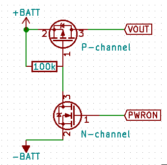
So that’s the basis of the input switch, but it doesn’t make a complete switching circuit - there’s no way to actually turn it on, because there’s no way to get power to the N-channel FET.
Power Button
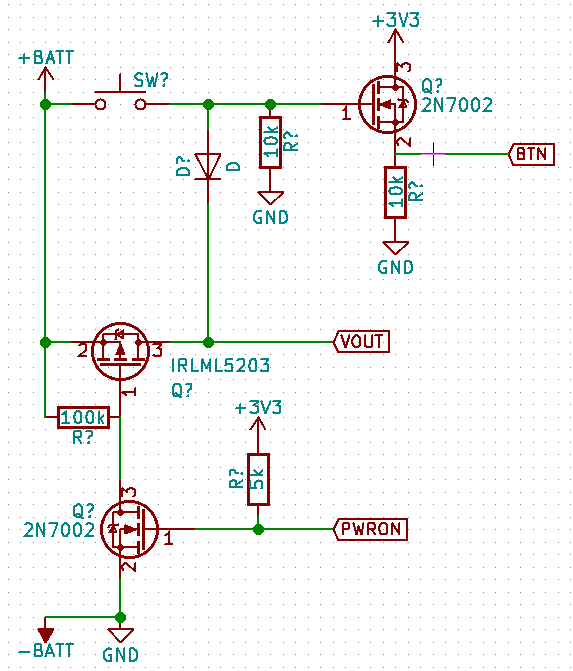
The basic idea is to add a push button switch which effectively bypasses the P-channel FET, directly passing the current to the load, just long enough for the load to switch on the powerup FET. On the schematic below you can see the button circuit. Adding a diode allows for the switch to drive another FET to send a logic-level signal to the Pi when it’s pressed with the power already on. Without the diode, the “BTN” output would be high all the time.
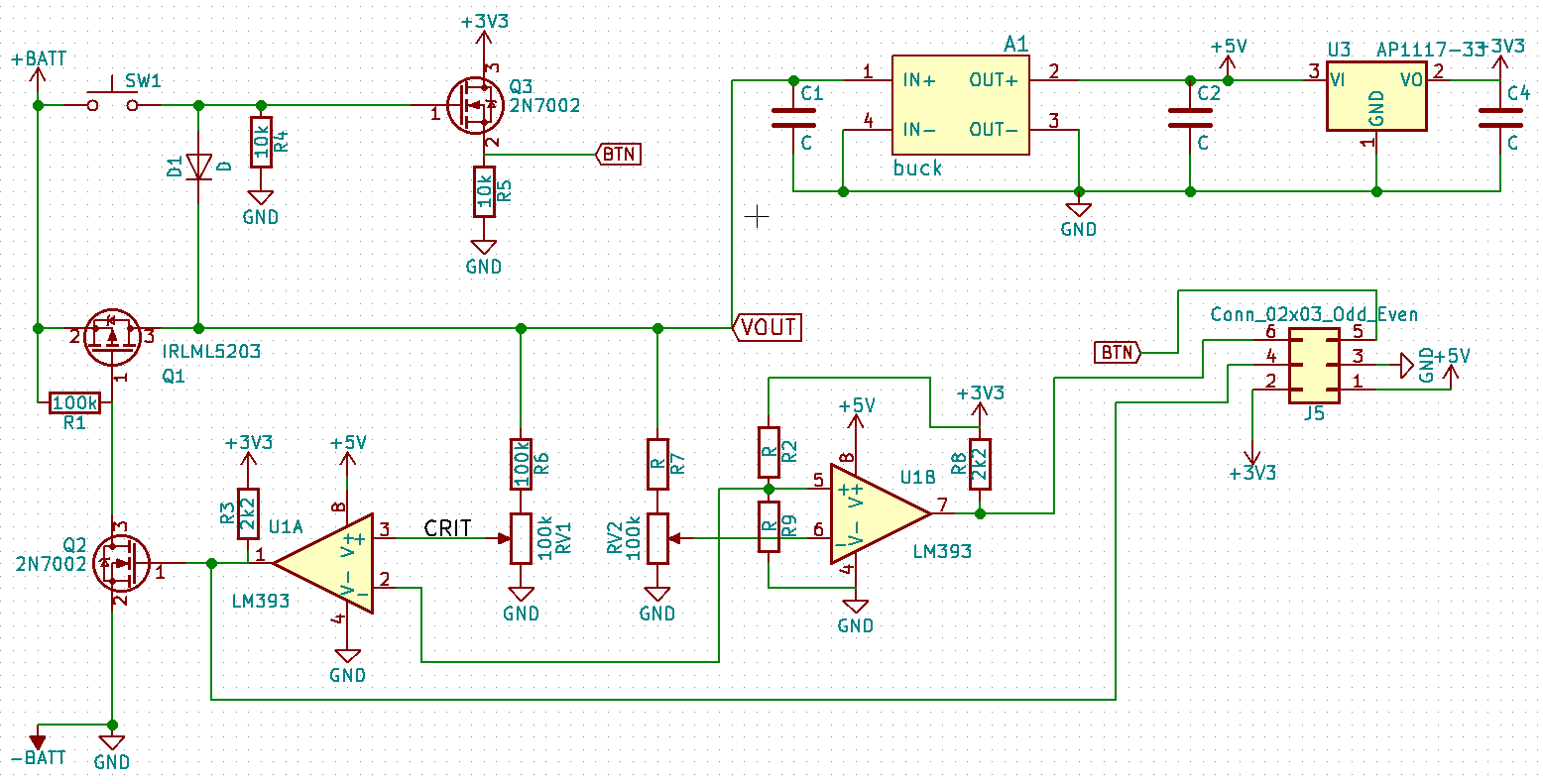
That completes the on/off portion of the circuit. Other aspects of the design are the voltage regulators, and an LM393 comparator to use for monitoring the battery.
Battery Monitoring
The LM393 contains two comparators - a device which compares the voltage on its two inputs and drives its output either high or low depending on which of the inputs is the higher voltage. We can use the comparator to keep an eye on the battery voltage (comparing it to a reference voltage), and notify the Pi when the battery voltage gets low.
I’ve wired up the other half of the LM393 to provide a “critical” battery level monitoring - when the battery reaches critical level, it will forcibly power off the circuit by pulling the PWRON pin low. This makes sure that even if my code on the Pi is buggy (or the Pi crashes, or anything similar), the battery will be protected with no software involvement.
The ‘LOW’ and ‘CRIT’ voltages are set by means of a pair of variable resistors, and the reference inputs of the comparators are wired to the output of a 3.3V linear regulator, to provide a stable reference voltage to compare the battery against.
Voltage regulators
The board has a DC-DC buck converter module, which is set to output 5V, to act as the power supply for the Pi. It should be good for an amp or two, and it’s the same type of module I used on the Basebot in the first PiWars, so I think it will be OK. Driving a Pi 3B+ it gets pretty hot, but it doesn’t seem to break a sweat on a Zero.
There’s also a 3.3V linear regulator, which uses the 5V supply as its input. That’s driving the logic for the stepper motor drivers, and will likely drive miscellaneous other digital bits. I could use 3.3V from the Pi directly, but it seemed nicer to have my own regulator rather than piggy-backing on the Pi.
Software
The last part of the puzzle is setting up the Pi to monitor/drive the inputs/outputs appropriately.
There’s four things needed:
- Pull PWRON high as soon as possible after boot
- Trigger a graceful shutdown when the button is pressed
- When the shutdown completes, drive PWRON low, to turn off the battery power
- Warn when the battery gets low (LOW goes high)
GPIO settings at boot
Earlier in 2018, the Pi firmware got a new config.txt
setting to let you
control GPIOs very early in the boot process. I use this directive to set the
PWRON pin to pull-up as soon as the firmware runs. This seems to happen about
two seconds after powerup, so I need to hold the button for two seconds to get
the system to boot up.
Update: I’ve got a pull-up on the comparator output, so this directive is actually unnecessary, and in-fact it prevents the low-voltage cut-off from working correctly. It seems that it was needed on the first board I built because of a soldering issue on the LM393
gpio=23=pu
Shutdown Button
There’s already a
device-tree
overlay
for triggering a shutdown from a GPIO, so making the pushbutton work as a
shutdown button is as simple as adding this line to config.txt:
dtoverlay=gpio-shutdown,gpio_pin=22,active_low=0
Now, whenever pin 22 goes high, the Pi will shutdown gracefully.
Poweroff
Graceful shutdown is only part of the story - when the shutdown completes, the PWRON pin needs to be driven low to turn off the power, otherwise the Pi will sit “halted” but consuming power forever (motors too).
Again, there’s already a handy DT overlay for that - we just need yet another
line in config.txt:
dtoverlay=gpio-poweroff,gpiopin=23,active_low=1
Now, when the shutdown completes, the kernel will drive pin 23 low, which will immediately kill the power and put the whole system into zero-power-consumption mode.
Low battery indicator
Keeping an eye for low battery is just as simple as monitoring a GPIO pin. I haven’t written the code yet, but when the battery gets low, the Pi can notice the appropriate GPIO pin going high, and will flash the LED on my PS4 controller red.