PCBs
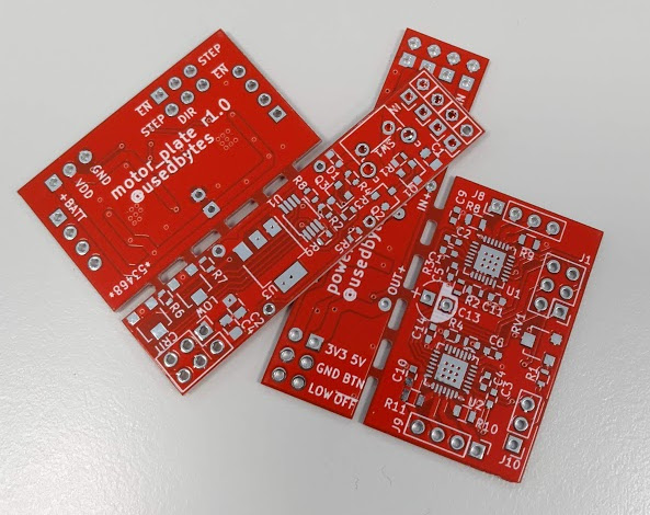
For Mini Mouse, I’ve designed two PCBs - one for motor drivers, and one for the power supply/control circuitry. These were my first boards using the open-source KiCad suite of EDA tools, having previously been an EAGLE user.
I got the boards made at dirtypcbs.com, panelising the two boards into a single 5x5 square. This is the third set of boards I’ve made with dirtypcbs, and I’ve always been very pleased with them.
Motor Drivers
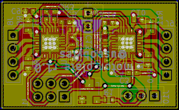
The motor driver board holds two A4988 stepper motor drivers and all the associated discrete components for them, The stepstick boards I bought basically copy the reference circuit for the A4988 exactly, so I did the same - copying the schematic out of the datasheet.
My board is actually about the same size as the two Stepstick boards it replaces. However, after doing some test fitting it seemed that wiring up the Stepstick boards would take up too much space in the body, and so I set about designing a PCB to reduce the total number of wires required.
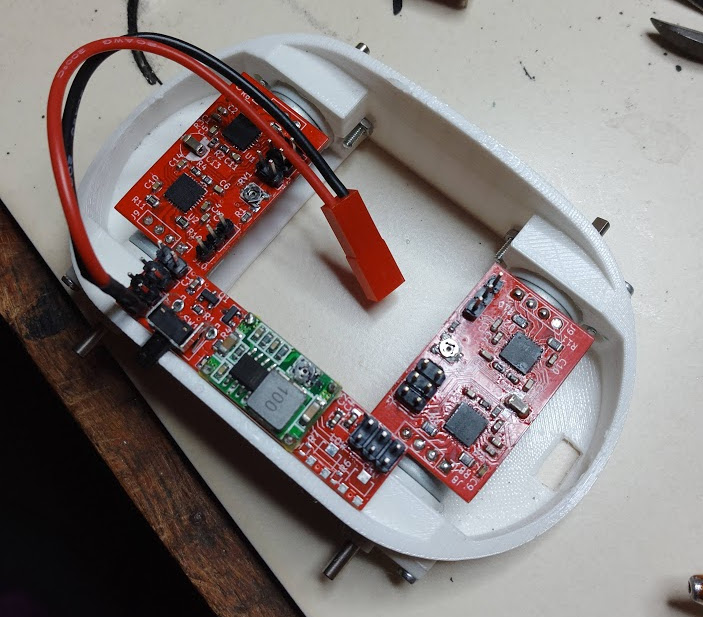
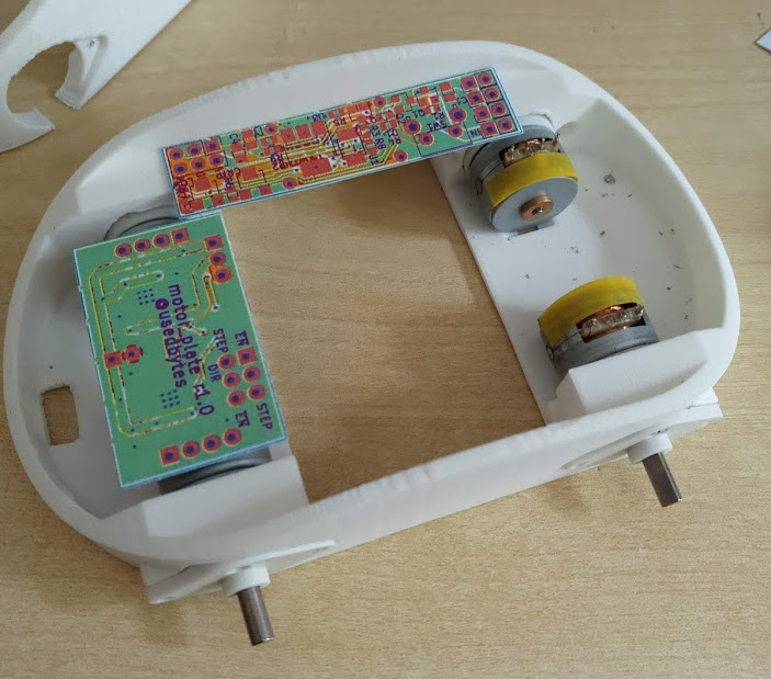
The physical design of the board is quite specific to Mini Mouse, with the PCB soldering directly onto the motors, bridging across the body of the robot. This again saves some space, avoiding the need to wire from the motors to the boards, though it does inflexibly fix their position.
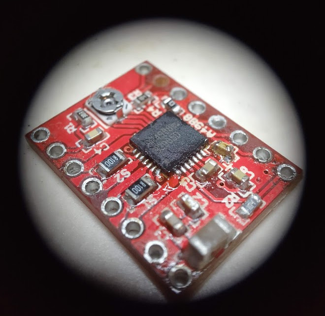
The A4988 comes in a QFN package, which I’d never tried to solder before. I figured I’d need solder paste and hot air, which I’d also never tried before. I didn’t buy any stencils with the boards, so I just applied paste with a cocktail stick, and then tidied up with a soldering iron after reflowing.
For practice, I de-populated, cleaned, and re-populated one of the original stepstick boards twice, to make sure my technique for soldering the QFN was OK. Actually, I have to say that the whole thing was incredibly easy. Solder paste is pretty magical in the way it reflows onto pads and avoids everything else. I’d never bought a bottle of flux before, but I really wish I had! Flux makes soldering small parts really easy.
For components, I de-populated the stepstick boards and re-used the components. This is far cheaper (and more convenient, really) than buying them directly.
I’m pleased to say that the boards worked first time, and I didn’t make any
mistakes in the layout. However, I do wish I’d included a pull-up resistor on
the sleep pin, to make the motors powered down by default. As it is, I need to
configure the Pi to pull the sleep pins high at boot (done via gpio=...
directives in config.txt).
Power Supply
The power supply circuit is discussed in much more detail in the power post, but it consists of:
- an electronic main power switch
- a pushbutton
- a DC->DC buck converter module
- low battery voltage monitoring
- a 3.3V linear regulator
The board is long and narrow, fitting down the side of the robot. It has battery input and motor voltage output at one end, and “logic level” outputs at the other end:
- 5V for the Pi
- 3.3V for other digital circuitry
- a low battery indicator signal
- an output from the pushbutton
- a “powerdown” pin, which will completely shut off the power if driven low
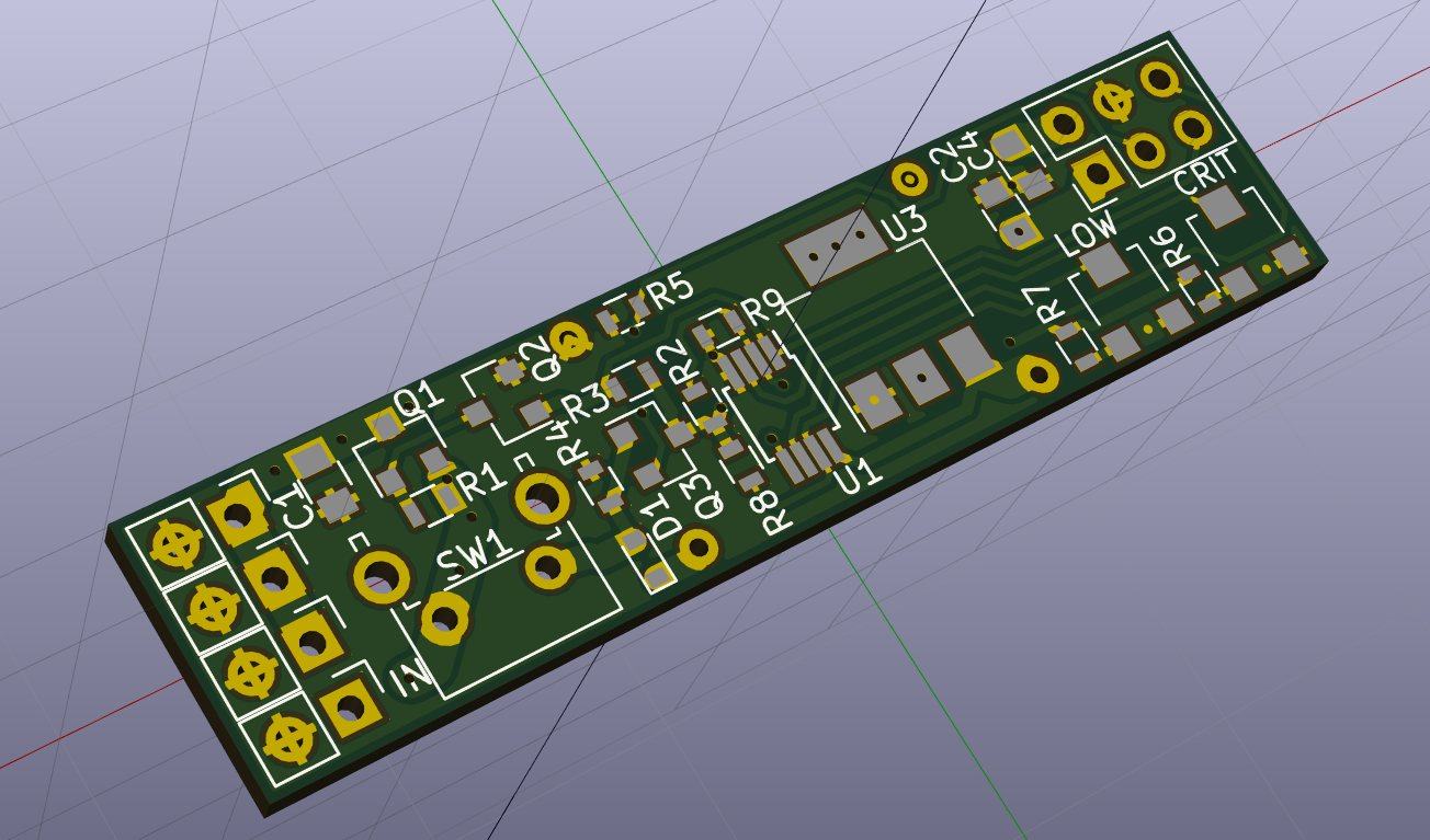
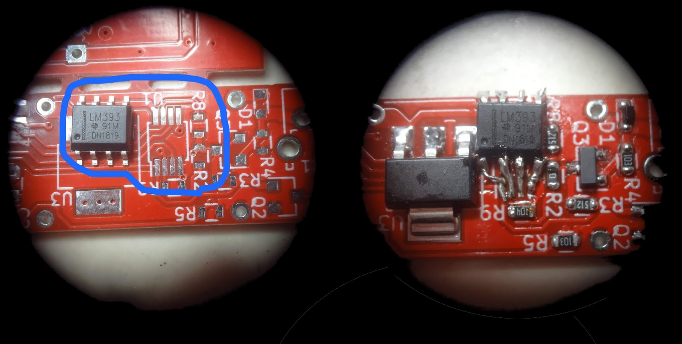
Unfortunately, I ordered the wrong package for my LM393, so on the first full board I had to hack on a larger package. This doesn’t seem to work properly, but I soldered up another board with the correct package and it does work OK.
The power PCB had a troubled beginning - after spending most of a day laying it out, I printed onto cardboard (always print your PCBs onto cardboard to test fit before you send them for manufacture!) and realised I’d laid the whole thing out the wrong way. I wanted it on the left hand side of the robot, but I’d built it for the right hand side. d’oh! Thankfully, PCBs always seem to go more smoothly the second time you lay them out, as you have all the required signal routing “internalised” in your mind. You have a good idea of where signals need to go, which bits have tricky crossings, and where you need to be careful of congestion.
The power board has a right-angle momentary push button, which will poke out of the side of the robot, which will work for power on and power off.
The image below shows how the two PCBs (two copies of the motor driver, and one power stick) sit in the chassis.