We're in!
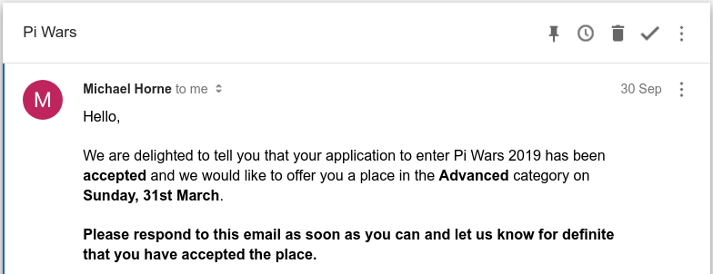
So last weekend Mike and Tim sent out the confirmations for Pi Wars entries, and Mini Mouse made the cut! We’re going to Pi Wars!
Doug on the Discord suggested the idea of sharing successful applications for people to look at to see if they can improve their chances next time - so here’s mine in case it’s useful.
It’s been a little over a month since my last post, but I have moved things forward a bit in that time.
Most of these things deserve a whole post of their own, but I’ll just put some brief status updates here.
Wheels
I’ve had my first wheels “done” for a while. They’re 3D printed in PLA, with a silicone O-ring inserted for grip. The very first revision was all plastic, but as you can imagine they had zero grip.
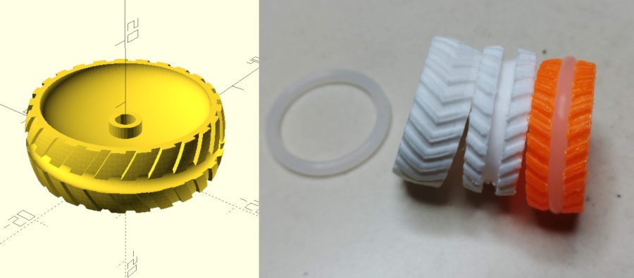
The new design works pretty well. I do lose some traction when they get dusty (which is almost certain for the hardboard Pi Wars courses), so I might do a new revision with two O-rings instead.
One problem I’m having is that as the stepper motors heat up, the PLA softens and the axles start spinning in the wheels. As a temporary fix I glued them on with a bit of PLA - but I bought some collars with grub screws to put in the middle of the next iteration, to hopefully provide a more secure attachment.
Orientation Sensor
I ordered a cheap Chinese breakout board for the Bosch BNO055 IMU and hooked that up. The thing is incredible! Less than £10, and fully filtered/integrated “9DOF” sensing (3 axis accelerometer, gyroscope and magnetometer).
I didn’t find a Golang library for it, so I wrote my own based on ghirlekar’s Python example on github.
What’s really strange is that even though the Python code worked fine, when I directly ported it to golang (same sleeps, same register writes) - and even confirmed with a logic analyser that the electrical signals were identical to within a few hundred µs - the Go code didn’t work!
I burned an evening trying to figure this out, and in the end stripped back to the absolute bare minimum required. It seems like ghirlekar’s code does a few unnecessary writes which mess up the sensor (no idea how/why the Python code works!). All you really need to do to get the sensor to spit out readings is:
// Assuming the following for accessing bno055 registers:
// bno055.write(register, value)
// bno055.read(register, nbytes)

// Go to NDOF mode
bno055.write(0x3D, 0x0C)
sleep_ms(30)

// Read one of the vectors (0x1A == Euler angles)
vector = bno055.read(0x1A, 6)

// Now vector contains the Euler angles as three 16-bit numbers
// Divide by 16 to get degrees
Software
Having built Bot Matrix last year, I had a good library of “stuff” for hacking together enough parts to get the robot driving (controller input, communication with my motor control daemon, sensor access). However, it was all thrown together quickly to get “something” working.
I paused a few weeks back to tear all that down, and restructure/rewrite the code to use the same general structure as Bot Matrix, to give a better base to build on.
The code is split into several modules, with different responsibilities:
main- The main module has the initialisation/setup code, and the main loop (which runs N times/second - currently 60)
- It’s responsible for polling the other modules and controlling state changes.
base- Represents the physical hardware of the robot. Controls the outputs (motors, LEDs, servos), and collects raw data from the sensors. Also holds physical characteristics about the rover - such as wheelbase width and maximum wheel speed.
interface- The interface module just handles input. At the moment that’s keeping an eye out for the PS4 controller appearing/disappearing and keeping track of button presses etc.
model- Responsible for reading input from sensors (wheel odometry, orientation sensor) and trying to figure out where the robot is. Right now it’s very crude and just uses wheel odometry for dead-reckoning positioning.
plan- The plan module is where the robot decides what to do. There are/will-be
several different plan modules, one for each task. The planners take input
from all the other modules, and decide what outputs to drive (e.g. what
motor speeds to set). At the moment I have two planners:
rc- The RC planner is just a remote-control routine. It listens for thumbstick input, and sets the motors accordinglywaypoint- The most basic autonomous planner. It gets the current robot position and orientation from themodelmodule, and tries to drive the robot back to position (0, 0).
- The plan module is where the robot decides what to do. There are/will-be
several different plan modules, one for each task. The planners take input
from all the other modules, and decide what outputs to drive (e.g. what
motor speeds to set). At the moment I have two planners:
I think I will add one a couple more modules, cv and telem, which will be
responsible for camera/CV activities, and telemetry communication respectively.
mini_mouse/bot
├── base
│   ├── base.go
│   ├── dev
│   │   └── dev.go
│   └── motor
│       └── motor.go
├── bot
├── interface
│   └── input
│       └── input.go
├── main.go
├── model
│   └── model.go
└── plan
    ├── plan.go
    ├── rc
    │   └── rc.go
    └── waypoint
        └── waypoint.go

9 directories, 19 files
I’ve also hacked up Bot Matrix’s camera code to get image output from the camera. Right now it’s just sending a low-resolution image over the network to the host-side UI (see below), but I’ll be working on proper integration with the core code ASAP.
Computer Vision
I started playing with OpenCV for some computer vision things. Focussing on two things to start with:
Horizon detection
For the maze, I plan to use just the camera to navigate. The basic strategy will be to find the horizon (well, actually the base of the wall) in each direction, and drive towards whichever horizon is the furthest away. When the robot reaches that “wall”, it will look for the next place to drive (hopefully being careful not to retrace its steps). So for that, I need to be able to detect horizontal lines.
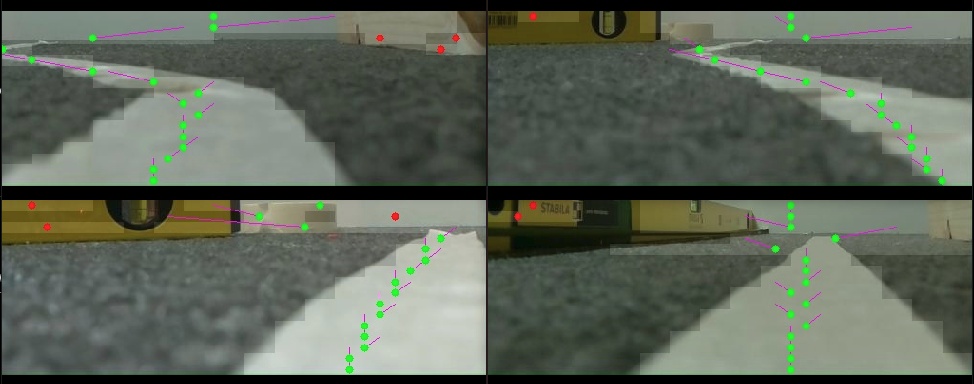
Messing around in Python with some Hough line transforms and gradient detection, I’ve got something sort-of working, but it will need a lot of refinement to be usable.:
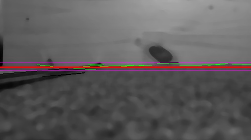
The black lines are lines which were detected but discarded because their angle was too steep. The purple lines show the region where lines might be considered to be part of the horizon (based on the standard deviation of the Y coordinates of all the detected line segments). The green lines are line segments which are thought to be part of horizon, and the red line is the eventual decision.
On this image you can see that detection fails, because a strong line is detected high up, which spreads the purple “window” and skews the average:
Line detection
For the straight-ish line speed test, I’ll try to use the camera to follow the white line. This should be a much easier CV task, and it’s going fairly well so far. My process is quite simple:
- Take camera image, and crop to keep only the bottom half (the ground)
- Downscale to 16x16 pixels
- For each row in the image, normalise the contrast so that the brightest pixel is 255 and the darkest is 0. This “stretches” the contrast to try and give the best possible separation between the white line and the black backround.
- Threshold the image, turning pixels above 127 -> White, and below 127 -> Black
- Find groups of white pixels in each row of the thresholded image
- Find the centre of each group, and use some heuristics to pick out which ones are likely to be the line.
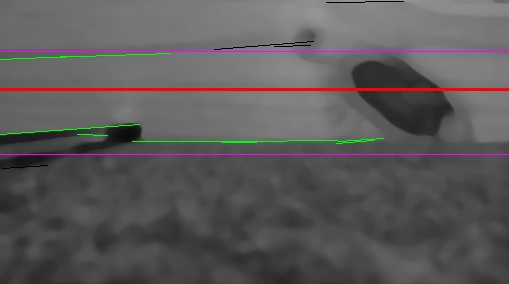
You can see the result on a couple of my test images below. The blocky overlay is the thresholded 16x16 image, and the purple lines are the “predicted” position of the line, used to pick out the correct white segment. Red dots are white segments which have been decided to not be part of the line:
Host-side UI and Telemetry
Lastly, something I wanted for Bot Matrix but never did was a proper UI for visualising what’s going on on the rover. I did implement a simple web interface for debugging and tuning my motor controller, but it never got any more sophisticated than that.
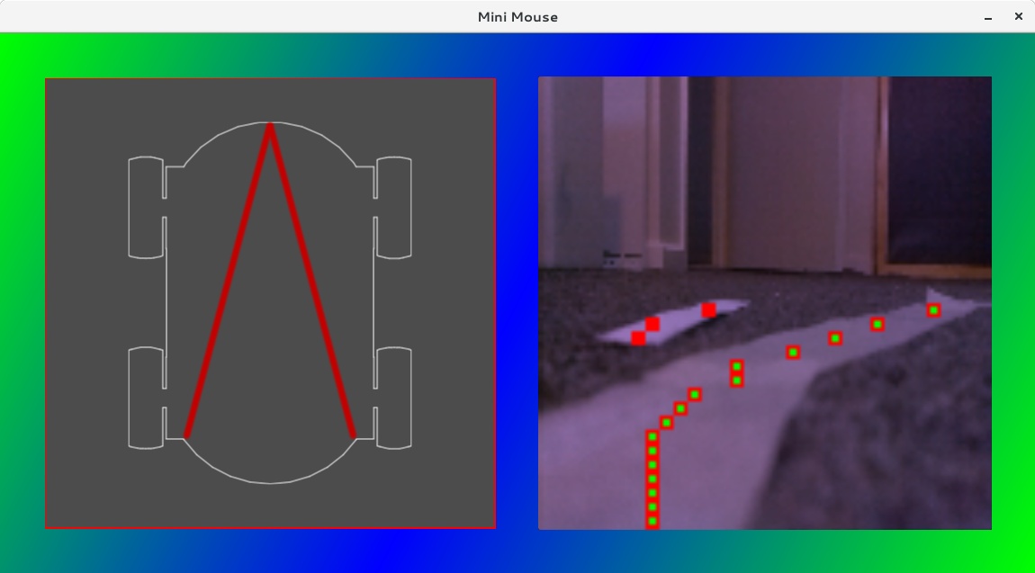
This time, I’ve hacked together a simple SDL + Cairo-based application which I should be able to use to show all sorts of information. It runs on a PC and connects to the robot over a couple of network sockets (one for readings/status, and one for streaming video data).
Right now I’m using it to show the orientation of the rover (left hand side), and the camera feed, with computer vision output overlaid (running line detection here). Note how it ignores the “misleading” bit of paper next to the real line
Source Code
Lastly, I’ve decided to use repo to manage my source code. You can find it all in my github, and the repo manifest is here
(The work in progress stuff isn’t uploaded yet, but will be as I start committing it)
And that concludes today’s brain-dump! I’ll do some more focussed blog posts in the coming weeks.