Final Hardware
It’s been a few frantic months of robot building between my last post and now, a decent portion of it being focussed on finalising the chassis. Since around September I’ve had my prototype chassis working, which has given me a great test-bed for software implementation testing and debugging the hardware design.
There were three main (known/intentional) limitations with the prototype chassis, borne out of a need to get it built and tested before I could finalize some of the details. Specifically:
- It had no proper battery door. The battery was held in with a piece of cardboard taped to the chassis
- It had no way to attach a lid. I wasn’t sure how the innards would really fit (on such a compact design, I can’t fully trust the CAD model for sub-millimetre accuracy)
- It lacked any way to add “attachments”, which are needed for the guns, Pi Noon and sample holder
However, it taught me several valuable things. It proved that everything fit, and that I could afford to drop the power supply PCB a fraction. It also showed that my motors get so hot that the shafts melt out of PLA wheels - and so I made new ones which have metal collars in the middle with grub screws holding the shafts.
So, lessons in hand, I set to building the final hardware. I was apprehensive about destroying the working prototype to build the new one, just in case something went catastrophically wrong. So, as suggested by Doug on the discord, I bought a new set of (identical) parts (motors, stepsticks, Pi Zero, camera, IMU).
Chassis
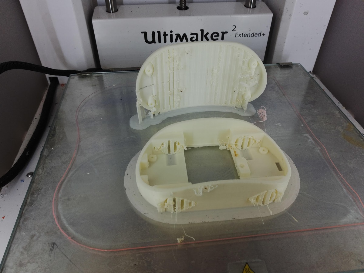
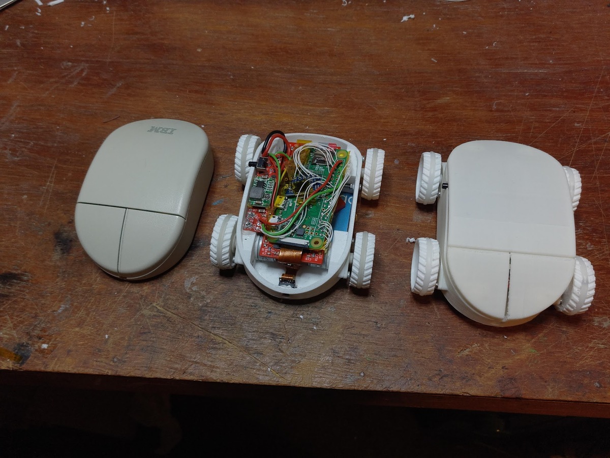
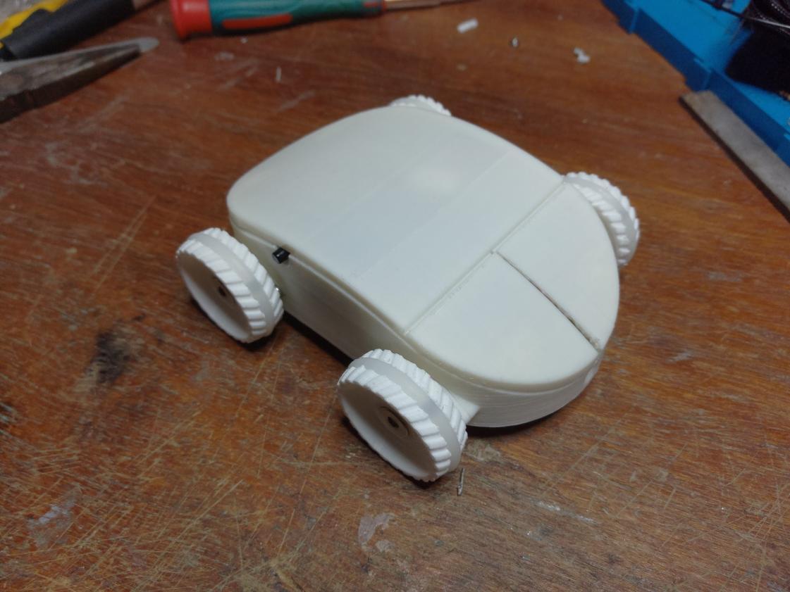
The final chassis addresses all of the above. It has a battery door held in by a bolt into a captive nut. It has an “auxiliary” port for attachments, consisting of two captive M3 nuts and a 4-pin connector for an i2c bus. It also has 4 holes for M2 bolts for holding the lid on.
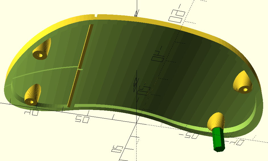
The lid is incredibly thin (somewhat accidental). At the highest point, the skin is only a single layer thick. It accepts four brass M2 spacers, which the bolts from the bottom half screw into to hold it on. Of course, from the outside, it looks like a mouse :-)
Electronics
As I mentioned, I didn’t use any of the parts from the prototype, which means I had to build a whole new set of electronics. The video below is a (terrible quality) time-lapse of what work goes into populating my PCBs. The footage came off one of the super cheap Chinese action cameras, with an Allwinner chipset. I’ve rooted it and dumped the firmware - a topic for a future post.
You can see how I’m harvesting the motor driver parts from the cheap and ubiquitous “stepstick” boards, and how I need to rework one of the QFNs after the first attempt to solder it was unsuccessful. Those small parts are hard! Useful tools for this kind of work include:
- Lots of tweezers, of various sizes
- Toothpicks, for applying solder paste
- Solder paste
- Hot air gun and soldering iron (obviously)
- Bottle of isopropyl alcohol
- Toothbrush for cleaning
- Liquid flux
- De-soldering braid/wick
- Magnification. I use a “loupe”, which is actually just a lens salvaged from a printer/scanner, and a Soviet binocular microscope.
- An old bathroom floor tile out of the shed, to protect your workbench from getting scorched
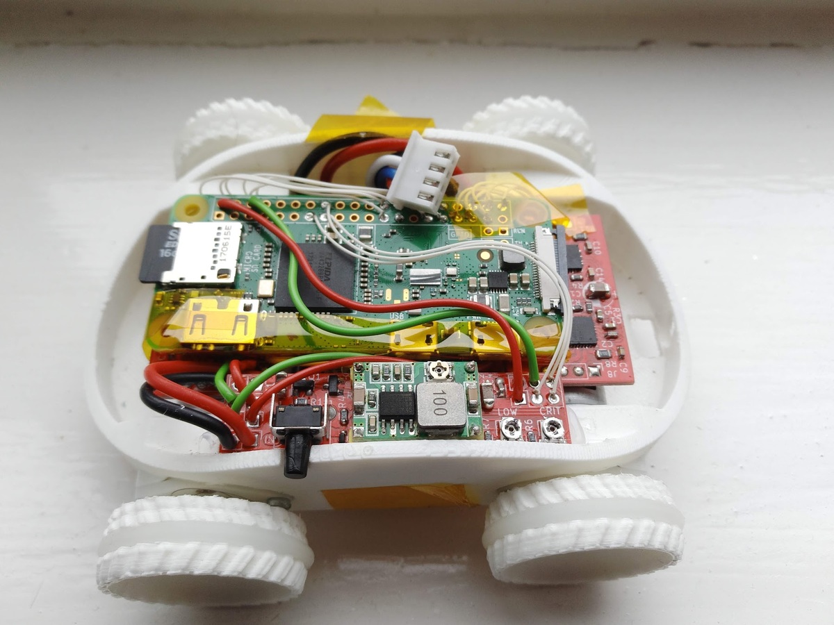
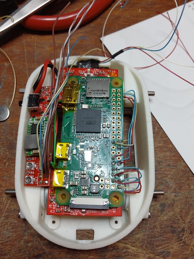
This time around, I spent a lot more time and care on the wiring. I used stiff enamelled wire for the main motor power bus, which helps keep the boards in place, and is easy to shape as needed. The 5V lines are multi-strand, off some reels I had lying around. Unfortunately it’s got PVC insulation which melts terribly. Everything else is tiny gauge Kynar wire, which is incredible stuff. The insulation will melt/burn off if you put the iron right on it, but won’t melt any further than that. It’s single core which makes it easy to shape, and it’s tiny so it doesn’t take up much space.
And with that all done, I’m ready to call the core robot complete.