M0o+ Boom - Part 1
The mechanical and electronic design of M0o+'s boom
My Pi Wars at Home 2022 robot M0o+ is intended to resemble a telehandler (long-reach forklift).
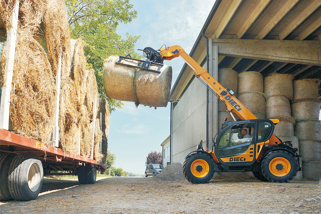
Image credit: Jacquesbotha, CC BY-SA 4.0, via Wikimedia Commons.
A fairly crucial part of a telehandler - the thing that makes it a telehandler, really - is it’s boom, which the forks (or other tools) are attached to and can lift and extend.
This post covers the mechanical and electronic side of M0o+’s telehandler boom. In a future post I will detail the Inverse Kinematics code which allows me to precisely position and move the end of the boom.
Initial concept and prototype
As far as I know, “real” telehandlers use hydraulic cylinders to actuate the lift and extension mechanisms of their booms.
While miniature hydraulics would be extremely cool, and it looks like there are products out there, it also sounds complicated, potentially very messy, and extremely expensive! So, I wanted to design a fully electronic solution for lifting and extending the boom.
I was conscious that for the Hungry Cattle challenge the boom was going to need to hold a moderate amount of weight (a few hundred grams), and after some sketching, I settled on a design which would mount two large static gears to the robot’s chassis, and then have a motor on the boom which would “climb” those gears.
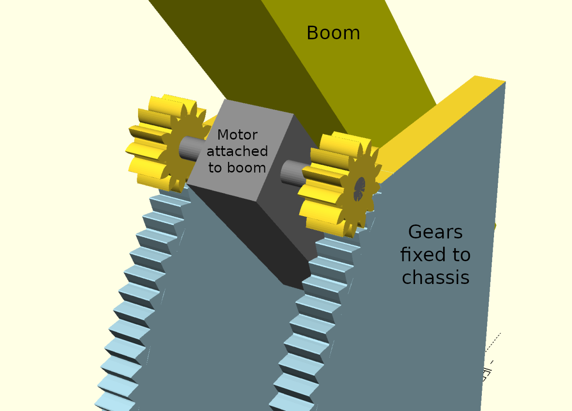
For the lift motor, I bought a dual-shaft worm drive N20 motor, and 3D printed the gears - both the large static ones, and the small pinion gears to put on the motor.
For extension, I bought some drawer runners, as a simple way to get a strong, rigid sliding joint.
In my initial tests, this seemed to work OK - even with full extension and some weight added to the end (in the form of magnets), the boom was able to raise and lower under motor power:
Satisfied that this plan could work, I moved on to other things, assuming I’d just design proper parts for the boom base, pivot, and extension mechanism (described below) at a later date. This was around the end of November 2021.
Unfortunately, for reasons which I never really got to the bottom of, the final design just didn’t work when I came back to it in January 2022.
I think the gears weren’t meshing well, causing a huge amount of friction, and the added weight of the extension leadscrew resulted in a mechanism which simply wouldn’t move.
So, I had to rather frantically go back to the drawing board on the lift mechanism!
Lift motor replacement
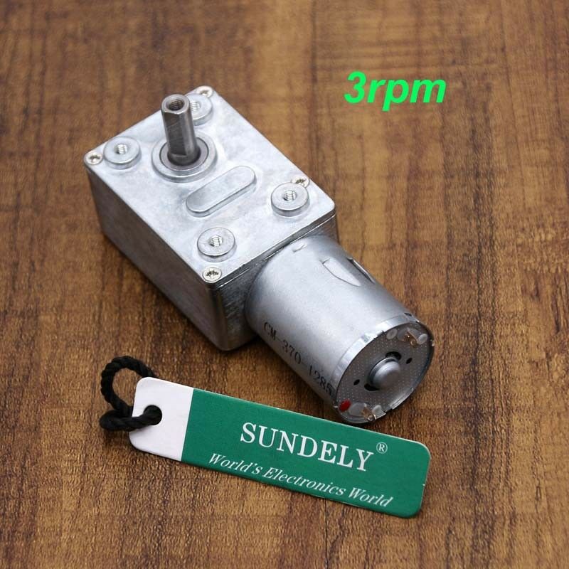
After spending some time trawling around on eBay, I found various sellers with these “GW370” motors, with the low-RPM variants claiming to have torques of 100-250 Ncm, which would be enough to give the lift capacity I wanted:
I wasn’t convinced a 3D printed part would be able to handle 200 Ncm directly from a 6 mm shaft, so I also bought some metal flanges to transfer the load from the motor shaft to the 3D printed boom.
With a little more CAD, I had a new boom assembly, and the new motor works really surprisingly well. The weak point is almost certainly the gearbox, but so far it’s survived.
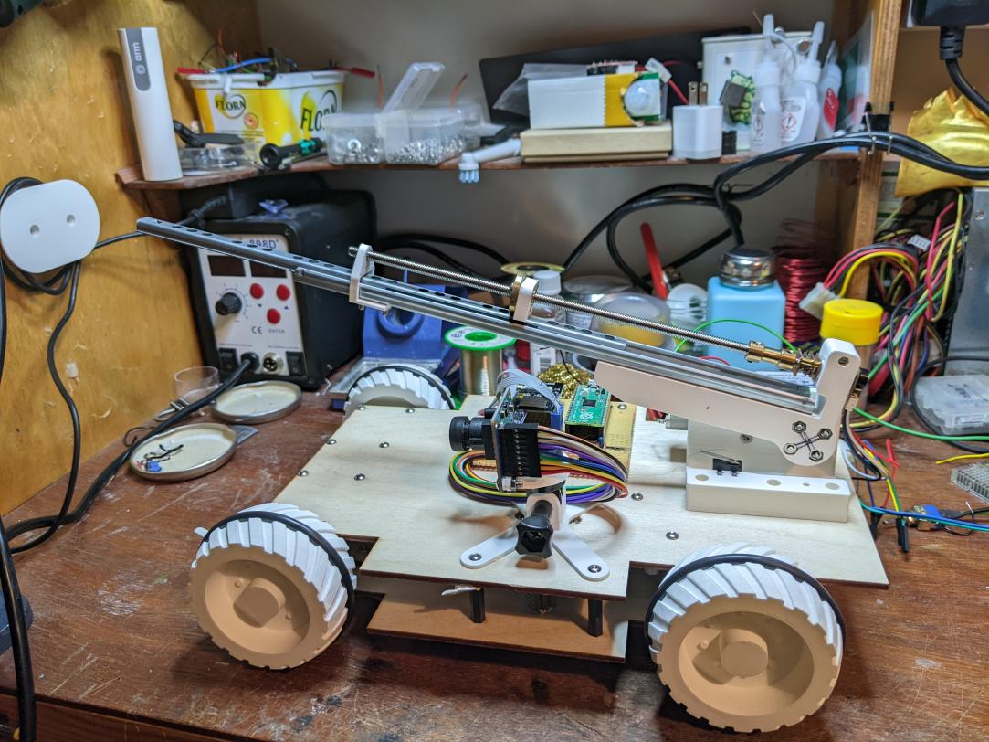
If you’re particularly eagle-eyed you may spot that the photos on this page are inconsistent with respect to which side the lift motor is mounted. I mirrored the assembly during development to make more space for the electronics board.
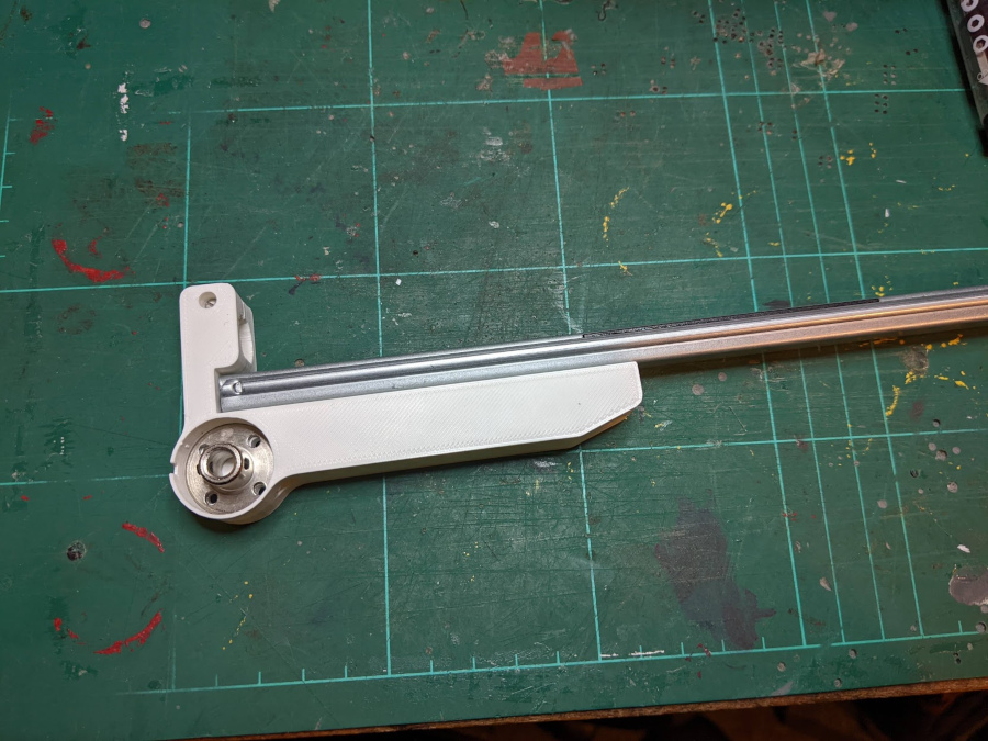
Extension
As I mentioned, for the sliding extension mechanism I’ve used a drawer runner. An absolute bargain at £2.68/pair from Screwfix.
This gives a really strong, rigid boom - the downside being that the steel runners are pretty heavy at around 70g each, eating in to my “lift budget”.
To actually move the runner, I bought a 5 mm trapezoidal lead screw with a brass nut from AliExpress.
Then, that’s connected to a small N20 “micro metal gear motor” which drives the screw, and some 3D printed brackets to hold the end of the screw and attach the nut to the drawer runner.
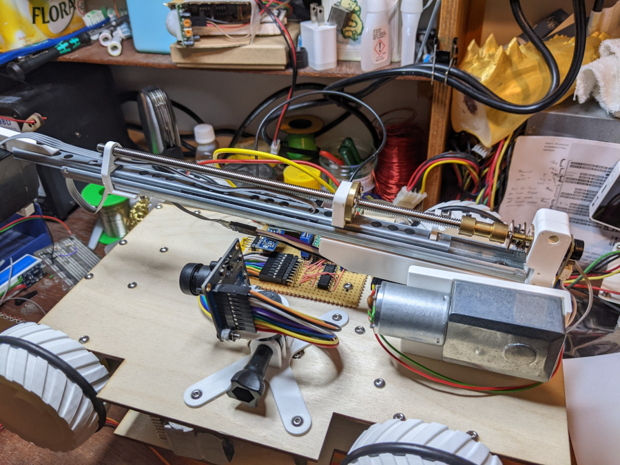
The result is a noisy (and heavy!) but functional linear actuator. You can see it in action in this proof-of-concept clip picking apples:
I have plucked my first apples! Remote control, and I don't think the attachment is in the legal size range, but still 😁 #PiWars (⚠️loud noise warning⚠️) pic.twitter.com/NfSVnltBKE
— Brian Starkey (@usedbytes) February 20, 2022
Electronics
Both motors are being driven by a DRV8837 dual h-bridge, which I just happened to have on-hand on a small breakout board. It can manage 1.5 A per channel, which is plenty for the stall current of both motors (a few hundred milliamps each).
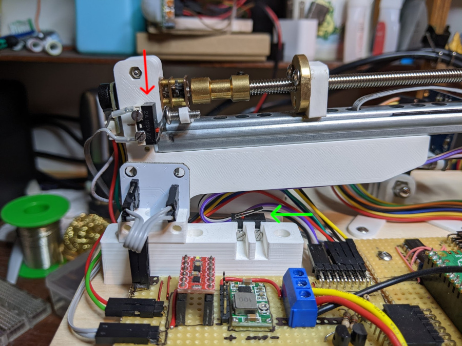
I’ve added limit switches to both “axes”, which allows me to return the boom to a known position to use as a reference - the process of “homing”, which is identical to what a 3D printer, laser cutter, or milling machine will do when it starts up.
To be able to position the boom autonomously, I need position feedback for both the lift and extension, so there’s some sensors to let me do that.
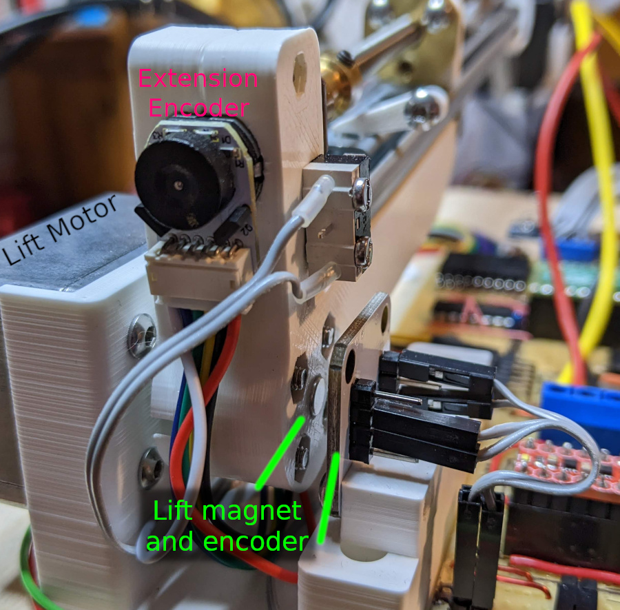
For determining the “lift” angle, I’ve got an absolute position magnetic encoder mounted opposite the motor axle, with a magnet on the boom, giving me direct sensing of the angle of the boom. It’s an AS5600 which can be easily found on eBay for a couple of pounds, with a breakout board and magnet.
For determining the extension, the N20 gearmotor has a traditional quadrature magnetic encoder mounted to the motor shaft (though I’m only using one channel). I don’t know the precise gear ratio of the gearmotor, so I just did a couple of experiments measuring the linear extension of the boom and the count reported by the encoder. This gives a conversion factor between the encoder reading and the boom extension in millimetres (it’s 137 counts-per-millimetre).
Boom-end electronics
Lastly on the electronics side, I want the ability to have servos and sensors mounted out on the end of the boom, to support the different challenge attachments.
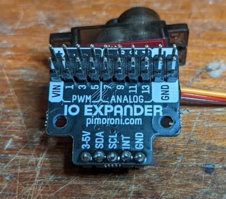
On the recommendation of @CannonFodder, I bought a Pimoroni IOExpander board, which is a fantastic little board, providing PWM/servo outputs, analog inputs and/or GPIO, controlled via i2c.
The IOExpander is “mounted” (well, not actually bolted on yet :-)) on the end of the boom. This poses an interesting challenge, because the wires for power and the i2c bus need to be able to extend and retract with the movement of the boom.
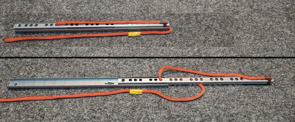
After playing around with a few options, I settled on a solution which feeds the wires down the inside of the drawer runner, and so far it’s working pretty well. The image below demonstrates the setup with some orange cord - imagine the brown end is fixed, wired to the IOExpander, and the yellow end is fixed to the static part of the boom, wired back to the Pico. There is some slack when the boom is extended, but it remains quite neat with the ribbon cable I’ve used.
I was slightly concerned about the signal integrity of the i2c bus over nearly half a metre, in a noisy environment with motors all around; but so far I haven’t had any problem.
To reduce the number of wires going down the boom, I’m using a 5 V supply for the IOExpander, which is enough to drive most servos. I made a level shifter with a couple of MOSFETs to handle the mismatch between the Pico’s 3.3 V IO and this 5 V bus.
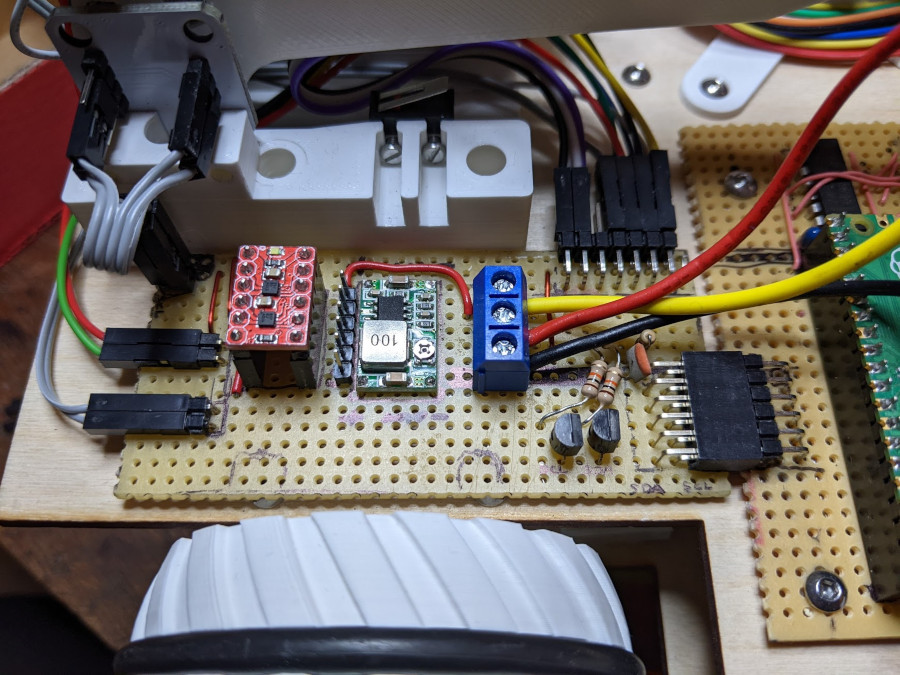
All of the boom-related electronics are mounted on a separate stripboard from the main electronics, with the H-bridge, level shifter, a DC-DC converter for the motors (the H-bridge can’t run at my “native” 3S battery voltage), and all the wiring for the switches and sensors. That plugs in to the main board with a right-angle header.
Fork levelling
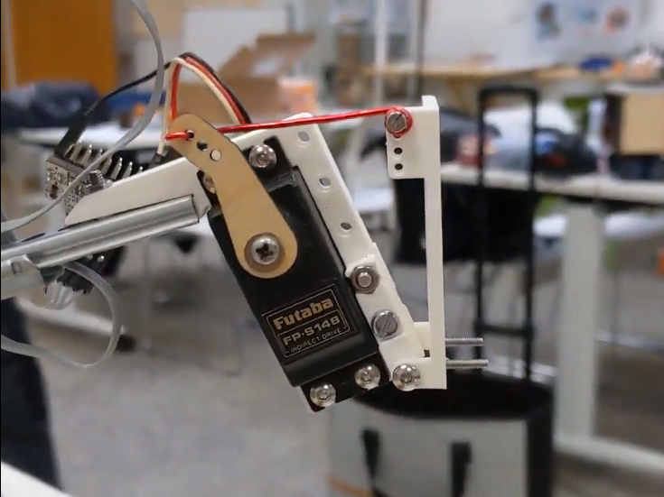
The last “core” part of the boom is a pivot and servo at the end which allows me to keep the the “forks” (or whatever other attachment) level as the boom lifts up and down.
If there was no extension mechanism, then this could be a simple mechanical linkage, but the fact that the boom can extend and retract makes a purely mechanical solution pretty challenging.
I already have angular position feedback to know what angle the boom is at, and I have the IOExpander out on the end of the boom which can drive servos, so I’ve hooked up a servo with a simple linkage which can pivot to keep the forks level.
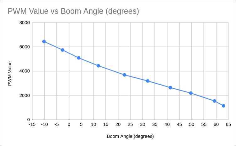
I did another simple experiment, adjusting the servo PWM value manually to make the forks sit level at different boom lift angles. This gives me calibration points to convert from boom angle to the required servo PWM value to make the forks level. Transferring that to the code and linearly-interpolating between the measured points does a pretty good job of keeping the forks level.
This is definitely one of the more satisfying parts of the build!
Fin
So that just about does it for the mechanical and electronic design of the boom. I still need to tidy up some of the wiring and properly mount the IOExpander, but functionally I’m not expecting to make any more changes.
Next post I’ll dive in to the maths required to be able to move it around with (some degree of) grace and precision.