Pico PIO Camera
Hooking up an OV7670 to Pico's PIO
This is a lengthy post which goes into lots of detail. The tl;dr is that the code is here: https://github.com/usedbytes/camera-pico-ov7670
In this post I’ll describe how I went about connecting an OV7670 camera module to the Raspberry Pi Pico that drive’s my Pi Wars at Home 2022 ‘bot M0o+. It’s all wrapped up in a separate library which should be easy-ish to incorporate in other projects.
Trying to get this camera working was the very first thing I did, as a sort of Pico “feasibility study” to decide if entering a Pico-based robot was practical. Initially I just bit-banged the interface and did get some results without too much effort, but things have escalated a fair amount since then:
So clearly there are some issues to work out, but this was bit-banged from an OV7670 on a Pico. PIO next. #raspberrypi #PiWars pic.twitter.com/yJFQFhU9Xk
— Brian Starkey (@usedbytes) September 14, 2021
OmniVision OV7670
The OmniVision OV7670 is a 640x480 (0.3 megapixels) CMOS camera, which dates from 2005(!). It’s apparently now discontinued but despite this is still readily available from all the usual places you’d look for cheap breakout boards.
You can get a module with an OV7670, a lens assembly, the necessary voltage regulators and 0.1" headers for less than £5 from a UK seller on eBay.
The interface to the camera consists of an i2c bus for configuring things like resolution and white balance, and a streaming parallel video interface for outputting the image from the sensor.
There are dozens of pages around the internet on interfacing this module, so I’ll focus on just the information that’s needed to make sense of the rest of this post.
Video interface
The video interface can be split into two parts:
- The synchronisation signals:
VSYNC,HREFandPCLK, which need to be used to keep track of which part of the frame the data is for. - The pixel data, which comes out on 8 signals,
D0-D7. One byte of data is transferred for eachPCLKcycle.
The camera “pushes” the images from the sensor continuously, at a fixed rate, whether the receiver is ready for them or not. With a bare OV7670 chip there’s no way to “pull” the frame at your own pace, because the sensor doesn’t have anywhere to store the pixel data1. This means on the receiving side, you have to “keep up” with the data coming from the camera.
To receive a frame from the camera, the process is something like this:
for each frame:
   wait_for_falling_edge(VSYNC)
   for each line in frame:
      wait_for_rising_edge(HREF)
      for each byte in line:
         wait_for_rising_edge(PCLK)
         byte = read_pins_parallel(D0, 8)
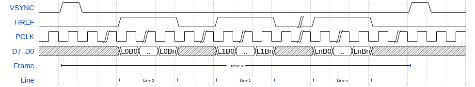
Timing diagram created with WaveDrom
The meaning of each byte depends on the configured pixel format. There’s a few
options available, but I only care about RGB565 and YUYV. In both of these
formats, two bytes are used for each pixel, so the number of PCLK cycles in
each line of the image is width * 2. However, for YUYV you need a complete run of
4 bytes to reconstruct 2 pixels, whereas for RGB565 you can take each 2-byte pixel
individually.
For RGB565:
| Signal | Byte 0 | Byte 1 |
|---|---|---|
| D7 | R4 | G2 |
| D6 | R3 | G1 |
| D5 | R2 | G0 |
| D4 | R1 | B4 |
| D3 | R0 | B3 |
| D2 | G5 | B2 |
| D1 | G4 | B1 |
| D0 | G2 | B0 |
For YUYV:
| Signal | Byte 0 | Byte 1 | Byte 2 | Byte 3 |
|---|---|---|---|---|
| D7..D0 | Y0 | U01 | Y1 | V01 |
YUYV Detour
A quick detour to YUV if you’re not familiar. This will be important when we get to packing/unpacking of the pixel data.
YUV is just a different way to represent colours. Where RGB splits each pixel into “redness”, “greenness” and “blueness”; YUV instead uses:
- Y: Luminance/Luma - The brightness of the pixel
- U/Cb: Chroma Blue - Blueness minus Luma
- V/Cr: Chroma Red - Redness minus Luma
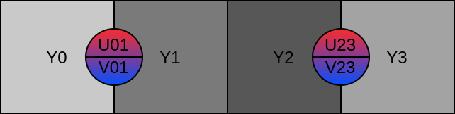
YUYV is a specific way of storing a YUV image. Because human eyes are much more sensitive to changes in brightness/luminance than they are to changes in colour/chrominance, it’s very common to throw away either 50% or 75% of the chroma samples as a crude form of data compression.
YUYV is a “4:2:2” YUV format, meaning 50% of the chroma data is discarded. Each pixel has its own Y value, but each pair of pixels in a line share a pair of U/V values. So in each set of 4 bytes received from the camera, we get 2 bytes of Y data, one for each of two consecutive pixels; and one byte each of U and V data, which apply to both of the pixels in the pair.
In a robotics context, YUV can be useful because if you just take the Y values, then you have a decent grayscale image, for something like line following; and if you take either or both of U and V, then you can easily identify colors (more on that on my earlier post about Mini Mouse).
Converting between RGB and YUV is possible, but it means a few multiplications and additions per-pixel, so if you want one or the other, it saves some processing if you can ask for the appropriate format from the camera directly.
Register Settings
The last point I want to make on the OV7670 itself is how much of a nightmare it is to configure. The datasheets/integration guides which are available on the internet don’t provide enough information to effectively configure the camera, and in some cases contradict each other.
There are various sources of “golden” register values, which I believe are sourced from OmniVision themselves, and they all contain tons of values and register addresses which either aren’t documented, or are marked as “reserved” in the data sheet(s).
After much frustrating messing around, I settled on using Adafruit’s reference values from their driver, which is a fairly minimal set and gives me the functionality I need (downscaling to 80x60 and both YUYV and RGB565 output).
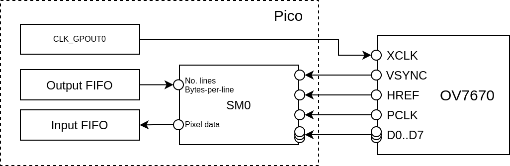
Hooking up the Pico and PIO
PIO on the Pico has totally flexible pin-mapping, so the camera can really be
wired to whatever pins you want. However, for parallel input the 8 data pins
should be wired to a consecutive run of 8 GPIOs, so that they can be shifted
in using a single in PINS 8 PIO instruction.
The other catch is that the OV7670 needs an external clock source, fed in to the
XCLK pin. You can generate that on the Pico in any number of ways, but I opted
to use one of the GPOUT clock generators in the RP2040, and the only pin which
can be used for this on a Pico is GP21 with clk_gpout0.
Converting the little frame program pseudocode above to PIO code is quite straightforward:
for each frame:
   wait_for_falling_edge(VSYNC)
   for each line in frame:
      wait_for_rising_edge(HREF)
      for each byte in line:
         wait_for_rising_edge(PCLK)
         byte = read_pins_parallel(D0, 8)
We need a counter for the number of lines, and a counter for the number of bytes in a line, which we’ll send in via the output FIFO. Then just loop over lines and bytes, putting the data into the input FIFO:
.program camera_parallel
.wrap_target
pull                          ; Pull number of lines from FIFO
out Y, 32                     ; Store number of lines in Y
pull                          ; Pull bytes-per-line from FIFO
                              ; Note: We leave bytes-per-line in OSR, to reload X each line

wait 1 pin PIN_OFFS_VSYNC     ; Wait for VSYNC to go high, signalling frame start

loop_line:                    ; For each line in frame
mov X, OSR                    ; Reload X with bytes-per-line
wait 1 pin PIN_OFFS_HREF      ; Wait for start of line

loop_byte:                    ; For each byte in line
wait 0 pin PIN_OFFS_PCLK      ; Wait for PCLK to go low
wait 1 pin PIN_OFFS_PCLK      ; Wait for PCLK to go high (rising edge)
in PINS 8                     ; Shift in 1 byte of data
jmp x-- loop_byte             ; Next byte

wait 0 pin PIN_OFFS_HREF      ; Wait for end of line

jmp y-- loop_line             ; Next line

.wrap                         ; Next frame
Aside: If “PIO v2” ever comes around, I think a “wait for edge” instruction would be a good addition.
This needs corresponding code for the CPU to load the programs, setup the PIO, drain the input FIFO, etc. Instead of reading the data from the FIFOs with the CPU directly, we can use DMA to copy from the PIO to a buffer in memory.
All that is left as an exercise for the reader I’m afraid, because I don’t have a decent copy of that implementation any more. My final full code is on GitHub but it’s significantly different from the program above for reasons described below.
Saving Pins
The approach above works great, but it uses loads of pins on the Pico, a total of 14!
SCLSDAXCLK- Must be GP21VSYNCHREFPCLKD0..D7- Must be contiguous
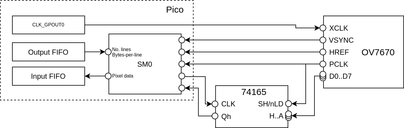
I can’t really afford to spend this many pins on my Pico, when I’ve also got multiple motors to drive and other sensors to talk to. So, I’ve added a 74165, parallel-in, serial-out shift register which will change 8 data pins to 1 data pin and 1 clock pin, a net saving of 6 pins.
I did try using the
XCLKpin as the shift register clock, instead of directly driving the shift register clock input – which would have saved an additional pin – but I couldn’t get the timing to work reliably, and my logic analyser isn’t fast enough to debug it.
I haven’t drawn a proper schematic, but this should give you the idea:
| OV7670 Module | 74165 | Pico | Pico (example) |
|---|---|---|---|
SIOC |
- | User decision | 1 |
SIOD |
- | User decision | 0 |
VSYNC |
- | base_pin + 2 |
18 |
HREF |
- | base_pin + 3 |
19 |
PCLK |
SH/nLD |
base_pin + 4 |
20 |
XCLK |
- | User decision | 21 |
D7 |
A |
- | |
D6 |
B |
- | |
D5 |
C |
- | |
D4 |
D |
- | |
D3 |
E |
- | |
D2 |
F |
- | |
D1 |
G |
- | |
D0 |
H |
- | |
| - | CLK |
base_pin + 1 |
17 |
| - | Qh |
base_pin |
16 |
| - | CLK_INH |
GND |
So what does this change in the PIO code? Well, instead of getting a whole
byte of data with a single in PINS 8 instruction, now we’re going to
need to manually shift the data from the external shift register, one bit at a time.
The program above is already using the two registers Y and X for the line
and byte counters, so there isn’t a spare register to use to count bits.
For now, let’s get the idea by just repeating the “read a bit” code 8 times,
using side-set to control the shift register CLK pin:
Confession: I haven’t actually tested these PIO snippets, but I hope they serve as useful illustrations
.program camera_serial_unrolled_loop
.wrap_target
pull                             ; Pull number of lines from FIFO
out Y, 32                        ; Store number of lines in Y
pull                             ; Pull bytes-per-line from FIFO
                                 ; Note: We leave bytes-per-line in OSR, to reload X each line

wait 1 pin PIN_OFFS_VSYNC        ; Wait for VSYNC to go high, signalling frame start

loop_line:                       ; For each line in frame
mov X, OSR                       ; Reload X with bytes-per-line
wait 1 pin PIN_OFFS_HREF         ; Wait for start of line

loop_byte:                       ; For each byte in line

wait 1 pin PIN_OFFS_PCLK         ; Wait for PCLK to go high (otherwise inputs are "transparent")
nop side 1                       ; side set CLK
in PINS 1 side 0                 ; Grab bit 0, clear CLK
nop side 1                       ; side set CLK
in PINS 1 side 0                 ; Grab bit 1, clear CLK
nop side 1                       ; side set CLK
in PINS 1 side 0                 ; Grab bit 2, clear CLK
nop side 1                       ; side set CLK
in PINS 1 side 0                 ; Grab bit 3, clear CLK
nop side 1                       ; side set CLK
in PINS 1 side 0                 ; Grab bit 4, clear CLK
nop side 1                       ; side set CLK
in PINS 1 side 0                 ; Grab bit 5, clear CLK
nop side 1                       ; side set CLK
in PINS 1 side 0                 ; Grab bit 6, clear CLK
nop side 1                       ; side set CLK
in PINS 1 side 0                 ; Grab bit 7, clear CLK
wait 0 pin PIN_OFFS_PCLK side 0  ; Wait for PXCLK to go low

jmp x-- loop_byte                ; Next byte

wait 0 pin PIN_OFFS_HREF         ; Wait for end of line

jmp y-- loop_line                ; Next line

.wrap                            ; Next frame
This obviously wastes a lot of code space (and is a bit ugly). Instead we can
use a second State Machine (SM) for the “inner” byte loop, giving us a brand
new X register to count bits in. This is also useful for other reasons,
explained later.
So:
- SM0 - Handles the “frame” timing
- SM1 - Just shifts in individual bytes, controlled by SM0
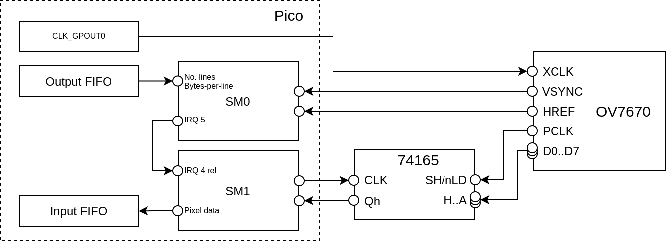
The SM0 program is nearly the same as before, but inside the loop_byte loop
it just triggers (and waits for) SM1 using IRQ 5:
.program camera_serial_sm_trigger
.wrap_target
pull                          ; Pull number of lines from FIFO
out Y, 32                     ; Store number of lines in Y
pull                          ; Pull bytes-per-line from FIFO
                              ; Note: We leave bytes-per-line in OSR, to reload X each line

wait 1 pin PIN_OFFS_VSYNC     ; Wait for VSYNC to go high, signalling frame start

loop_line:                    ; For each line in frame
mov X, OSR                    ; Reload X with bytes-per-line
wait 1 pin PIN_OFFS_HREF      ; Wait for start of line

loop_byte:                    ; For each byte in line
irq wait 5                    ; Trigger SM1 to shift in byte, and wait for it to finish the byte
jmp x-- loop_byte             ; Next byte

wait 0 pin PIN_OFFS_HREF      ; Wait for end of line

jmp y-- loop_line             ; Next line

.wrap                         ; Next frame
The SM1 program uses the X register to loop 8 times, but is otherwise similar
to before. Things get a little more complex here, using IRQ flags, side-set and
delay cycles, but it’s hopefully still understandable:
Note that
wait 0 irq 4 relis used, so that this same code can be used on different state machines. More on that below.
.program camera_serial_byte_loop
.wrap_target
.side_set 1 opt                  ; Use side-set bit 0 to drive CLK on the shift register

.wrap_target
set X 7                          ; Load the bit counter
wait 0 irq 4 rel                 ; Wait to be triggered by IRQ (4 + SM number), but don't clear it

wait 1 pin PIN_OFFS_PCLK         ; Wait for PCLK to go high (otherwise inputs are "transparent")

nop side 1 [1]                   ; side set CLK
loop_bit:
in PINS 1 side 0 [0]             ; Grab a bit of data, clear CLK
jmp x-- loop_bit side 1 [1]      ; Next bit

wait 0 pin PIN_OFFS_PCLK side 0  ; Wait for PXCLK to go low
irq set 5                        ; Tell the frame loop that the byte is finished

.wrap
This uses 9 fewer instructions in total than the single SM “unrolled” version, but uses up 2 State Machines.
I refer to the Raspberry Pi Pico C/C++ SDK documentation and plead innocence:
There is no need to feel guilty about dedicating a state machine solely to a single I/O task, since you have 8 of them!
Multi-plane data
The other reason for using multiple state machines, is it lets us easily use different buffers for the Y, U and V data. This is handy, because if you only want a greyscale image, you could ignore the U/V data entirely.
Or, if you only want the V data to look for “red” things (spoiler alert), then you can get the PIO/DMA to put all that V data into its own buffer, and you don’t need to worry about skipping over the Ys and Us in your image processing code.
To do this, we tweak the above SM0 program ever so slightly, so that instead of always triggering SM1 for each byte, we can replace that loop with different code for different data layouts, triggering different SMs.
Importantly, this means that the X counter in SM0 doesn’t count bytes any more, it
counts “chunks”, where the meaning of a “chunk” depends on the pixel format.
For YUYV, a “chunk” would be 4 bytes, whereas for RGB565 it might be only 2 bytes.
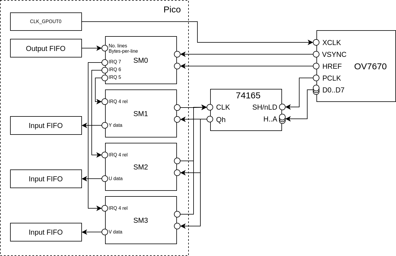
For using a separate state machine for Y, U and V, giving three separate buffers, SM0 looks like so (note “chunks-per-line” not “bytes-per-line”):
.program camera_serial_sm_chunk_trigger
.wrap_target
pull                          ; Pull number of lines from FIFO
out Y, 32                     ; Store number of lines in Y
pull                          ; Pull chunks-per-line from FIFO
                              ; Note: We leave chunks-per-line in OSR, to reload X each line

wait 1 pin PIN_OFFS_VSYNC     ; Wait for VSYNC to go high, signalling frame start

loop_line:                    ; For each line in frame
mov X, OSR                    ; Reload X with chunks-per-line
wait 1 pin PIN_OFFS_HREF      ; Wait for start of line

loop_chunk:                   ; For each chunk in line
irq wait 5                    ; Trigger SM1 to shift in Y0
irq wait 6                    ; Trigger SM2 to shift in U01
irq wait 5                    ; Trigger SM1 to shift in Y1
irq wait 7                    ; Trigger SM3 to shift in V01
jmp x-- loop_chunk            ; Next chunk

wait 0 pin PIN_OFFS_HREF      ; Wait for end of line

jmp y-- loop_line             ; Next line

.wrap                         ; Next frame
Because the camera_serial_byte_loop shift register program above used a
relative IRQ number in wait 0 irq 4 rel, we can use that exact same code on
state machines 1, 2 and 3 to handle the Y, U and V data respectively. SM1 gets
triggered twice per chunk, because there are 2 Luma samples per chunk.
If instead we wanted to put YUYV data into a single buffer, we can use just SM0 and SM1 and replace the pixel loop with:
loop_chunk:                   ; For each chunk in line
irq wait 5                    ; Trigger SM1 to shift in Y0
irq wait 5                    ; Trigger SM1 to shift in U01
irq wait 5                    ; Trigger SM1 to shift in Y1
irq wait 5                    ; Trigger SM1 to shift in V01
jmp x-- loop_byte             ; Next byte
Or separating Y from UV:
loop_chunk:                   ; For each chunk in line
irq wait 5                    ; Trigger SM1 to shift in Y0
irq wait 6                    ; Trigger SM2 to shift in U01
irq wait 5                    ; Trigger SM1 to shift in Y1
irq wait 6                    ; Trigger SM2 to shift in V01
jmp x-- loop_byte             ; Next byte
Or RGB565, with only 2 bytes per chunk instead of 4:
loop_chunk:                   ; For each chunk in line
irq wait 5                    ; Trigger SM1 to shift in Byte 0
irq wait 5                    ; Trigger SM1 to shift in Byte 1
nop
nop
jmp x-- loop_byte             ; Next byte
In fact, we can patch that loop_chunk loop at runtime depending on which pixel
format the code wants!
Final Code
With all that background above on how the code works, you should be well equipped to understand the eventual implementation at https://github.com/usedbytes/camera-pico-ov7670.
I’ve tried to make that a library which can be easily integrated into other Pico projects, but I haven’t put much effort into making it particularly configurable - for example the resolution is fixed at 80x60 pixels, and it doesn’t have the “parallel input” implementation, only serial input using an external shift register.
Feel free to submit patches to address some of the shortcomings!
In particular adding the necessary code to support parallel input would be really simple based on the code above. I don’t have a board wired up for that circuit any more, but maybe I’ll come back to that another day.
Integration woes
I did all of the development of this code on a very densely populated breadboard, and it worked great!
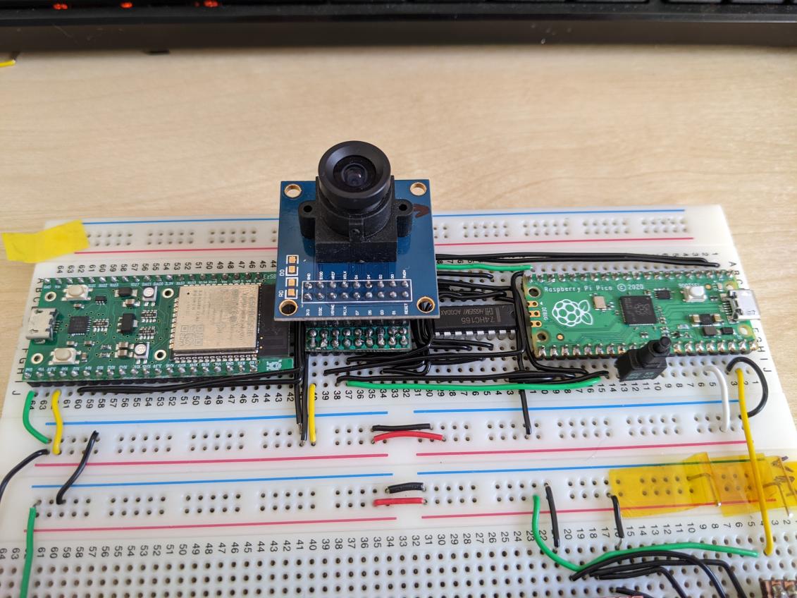
When I came to transfer this over to the robot, I ran in to tons of problems with signal integrity. Apparently in all my frustration/dispair, I didn’t save a single picture showing the problem!
I’m still not 100% sure what went wrong, but I re-soldered the circuit 4 times which was super tedious when there’s 20+ signals to wire on stripboard by hand. I also tried various different cables (including plugging in directly) to connect the camera to the board.
This cable I made doesn't work, but I wanted to share how nice it looks before I dismantle it any further. 😞🌈 #PiWars pic.twitter.com/dXPL6l3x5w
— Brian Starkey (@usedbytes) January 30, 2022
Wrapping a ribbon cable in foil (not electrically connected) seemed to work, but in the end I’ve settled on using separated jumper wires, and lots of fiddling with PIO delay cycles and OV7670 clock rates, to get a set-up which is working reliably.
Something to do with crosstalk or interference when they're inside the sleeve like that. Works fine as loose wires pic.twitter.com/CeYjkrUdSv
— Brian Starkey (@usedbytes) January 30, 2022
I wasted nearly 2 weeks of making time just getting the camera to work “in-situ” on the robot, so I’m not terribly motivated to sink more time into it just now. However, with those problems solved I was able to get the robot to follow a red blob, which was super satisfying :-)
After an extremely frustrating week of debugging electrical issues, this is intensely satisfying 😌 Everything being done by a @Raspberry_Pi Pico (which is a beast, "find the red blob" takes ~200us) #PiWars pic.twitter.com/njavAfDvp6
— Brian Starkey (@usedbytes) January 23, 2022
I’ll write more about the image processing as I start to come up with solutions for the Pi Wars challenges.
-
There are similar, more expensive modules which include an FPGA and a framebuffer RAM, which you can then “pull” the frame from using SPI, but with PIO there should be no need for this, the Pico is fast enough to capture the streaming data from the sensor. ↩︎