Autonomous Challenge: Blast Off

Blast Off: the Straight-ish Line Speed Test is, to my mind, the easiest of the three autonomous challenges in this year’s competition. As such, it’s the one which I started working on first.
The task is to get from one end of the course to the other as quickly as possible. There’s effectively two feasible options:
- Follow the walls
- Follow the white line
Given that I don’t have any side-facing sensors to follow the walls, to me the easiest option looked like following the white line.
My plan was simple: treat the camera like a line sensor. Traditionally, for line following, you have a line of very simple sensors which just give a black/white (0/1) reading. With one of these sensors you can tell whether you’re over the line or not. With 3-5, you can tell whether the line is to the left or right of the robot.
So, given that - if I can get a 5 pixel-wide image from the camera, where each pixel is the equivalent of a single line sensor, I should be able to follow the standard approach for line following.
I already covered thresholding in another post, which gives us pixels which act like line sensors - so we’re already half way there.
Pi Camera
The first thing needed is obviously to get pictures from the camera. For Bot
Matrix I already wrote code to access the camera via Broadcom’s MMAL
Multimedia Abstraction
Layer. To begin
with, I just used that, sending the pictures over a network socket to the main
bot process.
There’s one significant disadvantage to this approach: Copying. The ISP (camera) hardware in the Pi’s main chip writes the image data into a buffer in memory. To send it over a socket, you have to copy the data out of that buffer and into the “socket” (or, at least, a buffer representing the socket). The kernel then copies that into the receiving process, and that process copies it into it’s own buffer. That’s a lot of shuffling bytes around, which is inefficient. For small images, the overhead is miniscule - but the number of bytes in the buffer increases proportional to the square of the image dimensions, so it soon adds up. While my line following images are very small, I had much higher resolutions in mind for other challenges.
It’s better for performance and simplicity to access the camera directly from
my golang bot process, so based on the Bot Matrix C code I wrote a pretty
simple golang wrapper. You can find that library here:
https://github.com/usedbytes/picamera.
(Note that it’s possible to mitigate the performance issues without needing to be in the same process - but I shan’t go into those here. Look up buffer handle sharing)
Downscaling
For my line sensing, I only want very small images - in this case, just 16x16 pixels. The camera natively is more like 2500x2000 pixels, which means I need a way to reduce the size. Doing this in software is really slow, and CPU cycles are at a premium on the Pi Zero. Thankfully, the image processing hardware in the Pi has a dedicated scaling block which we can use to get whatever resolution we like.
It’s not well documented - but the component is called “vc.ril.isp”, and my
picamera library takes care of using it if the output image you request is
smaller than what the camera can natively provide. It’s also exposed in the
low-level
API
of the Python picamera library.
In golang, using my library, getting the images I need looks like this:
func main() {
	camera := picamera.NewCamera(16, 16, 60)
	if camera == nil {
		panic("Couldn't open camera")
	}

	camera.SetTransform(0, true, true)
	camera.SetCrop(picamera.Rect(0, 0.0, 1.0, 1.0))
	camera.SetFormat(picamera.FORMAT_YV12)

	camera.Enable()
	for i := 0; i < 10; i++ {
		frame, err := camera.GetFrame(1 * time.Second)
		if err != nil {
			fmt.Println(err);
			break
		}

		useFrameForSomething(frame)

		// frame.Release() is very important! If you don't release
		// your frames, GetFrame() will stall after 3 frames.
		frame.Release()
	}

	camera.Close()
}
Finding lines
After thresholding the image, we should be left with white pixels representing the line, and black pixels everywhere else. However, nothing’s perfect, and so there’s always the possibility of erroneous white pixels which aren’t related to the line at all.
The first way to mitigate this, is to crop the camera image, so that we only look at the bottom half. The line will always be on the floor, so there’s no point in looking above the horizon.
After that, the job of the line detection algorithm is to decide which of the white pixels belong to the line and which don’t.
My algorithm starts with an assumption that a white pixel (or group of white pixels) at the bottom of the image is likely to be on the line. Then, it looks for the (group of) white pixels on the row above which are closest to those it just identified. As it goes, it uses the direction from one row to the next to decide where the line is most likely to be. By having this “prediction” of where it expects to find the line, it’s able to ignore white points which are not part of the line.
The image below shows a sample picture, with the the low resolution thresholded version blended on top (faint white blockiness). The dots mark (groups of) white pixels - with green dots being considered “part of the line” and red dots being considered not part of the line. The purple lines show the “direction” prediction vector which is used to decide which dots should be red versus green.
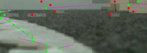
As you can see, the tape line heads off to the left of the image, and the green dots track it. There’s a few white pixels towards the top centre which are not part of the line - and they’re correctly coloured red. At the very top of the image, we end up above the horizon and all bets are off, but you can at least see from the purple lines why it chose the ones it did.
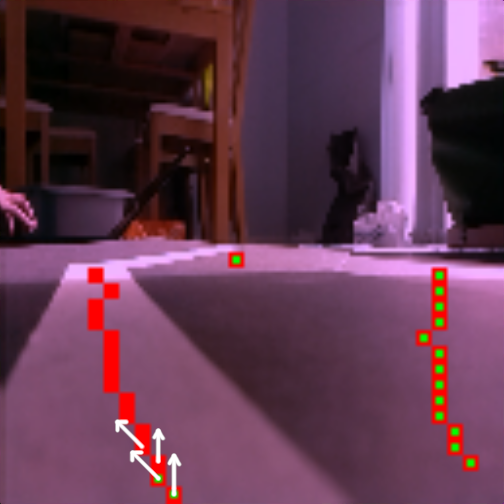
Without this “prediction”, the line detector can get easily confused by other bright points in the image, as shown in the picture below. Here red+green means the algorithm thinks the point is “on the line” and red means “off the line.” The prediction implementation was completely broken here - with catastrophic results. You can see that the line is picked out by the thresholding (it’s covered in dots) - but incorrectly classified as not being the line (they’re red instead of red+green)! That’s the kind of thing which will cause a failure on the day if the course is unevenly lit (which it usually is).
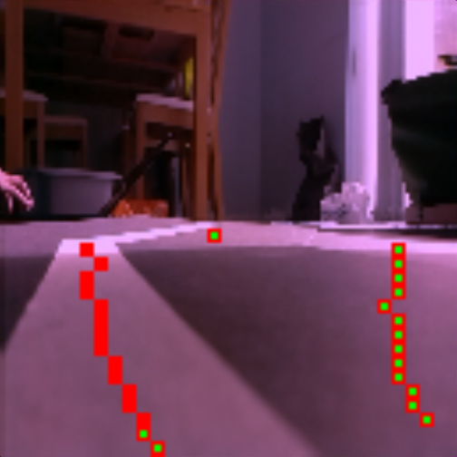
With prediction, this image would be classified correctly - the direction prediction from the bottom point to the next up would guide the algorithm to the left, and it would pick the correct line of points.
Following lines
With all of the above, we’ve got a reliable way to identify which pixels in our image represent the line. Effectively, a 2D array of line sensors, instead of a 1D row of them. How do we take that and turn it into driving along the line?
I decided to try and pick out an individual row from the image, to emulate the traditional single row of line sensors. But which row to pick? If we pick one which is too close (too low down in the image), we won’t have time to react - remember the robot is moving, and the image is going to be up to 1/60th of a second old by the time we process it - so we might lose the line easily. Pick one which is too far away (too high up in the image) and we’ll react too early, failing to closely track the line. We want a goldilocks row; just right.
We can’t just blindly pick the middle row of the image, because the thresholding might not be perfect (meaning gaps in the line), or we might not be able to see a lot of line because we’re nearly off it.
Here’s the approach I take:
- Find the “nearest” row which contains a point on the line - call it
nearest - Find the “furthest” row which contains a point on the line - call it
furthest - Find the row halfway between
nearestandfurthest:mid = (nearest + furthest) / 2 - Pick the first row containing a point on the line which is at least as far away as
mid.
Side note: In writing this post, I’ve just spotted what I’m pretty sure is a bug in the code, which means it’s probably picking a row which is “too close” in some situations
After picking a row, we see which column the line is in. If it’s to the left, the robot should turn left. If it’s to the right, it should turn right. If it’s in the middle, go straight. With that, we can follow a line (…really slowly):
To improve the speed, we need to improve the algorithm. The basic idea is to drive straight quickly and only slow down to turn. The amount of slow-down is proportional to how far the line is from the middle of the frame, and the same with the speed of turning.
With that one simple improvement it can manage to go quite a bit faster, but this is quite a windy course so it never really reaches full speed. You can still see how it speeds up on the straighter parts:
With the addition of “Boost” mode to increase the maximum speed, I’ve got something which I’m reasonably happy to take to the competition: