M0o+ Software Overview
An overview of the Pico code for M0o+
I’ve written a number of posts now about different “building blocks” which make up M0o+:
- The bootloader
- The network/bluetooth interface
- The chassis
- The camera
- The boom, parts 1, 2, and 3.
There’s one crucial element missing from that list, which is needed to turn a collection of parts into an actual functioning robot than can compete in Pi Wars: The Software.
I always find that this is the “hump” of a project. Building the individual blocks is time consuming (there can be a lot of them), but they’re varied which makes them interesting, and you get a good sense of accomplishment when you get one of them working.
Then, several months down the line you’ve got this figurative pile of bits which work individually, but bringing them together means there’s quite a lot of somewhat difficult software work, with no real intermediate progress. There’s really no new “milestones” or visible progress until the whole lot is done and you can finally move past the “making building blocks” stage into the “making things with the blocks” stage.
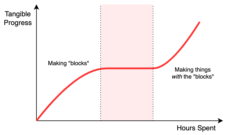
Honestly, this is where most of my projects get stuck and abandoned: taking something from a hacked together prototype to a working platform that you can use to do stuff just never seems that fun. Thankfully, Pi Wars gives a very real motivation with a very real deadline to get you over that “hump” 😄
Eventually, once you’ve settled on an approach and seen it through, if you’ve done it well, progress becomes fast again as you put together solutions for the challenges using the foundation you just built.
Very high level view
The Pico has two cores which execute independently, and I’ve had the intention from the very beginning that I’d dedicate one core to asynchronous “background” tasks, like managing the motors and sensors, and the other one to the actual challenge tasks, like deciding where to drive and how quickly.
This is similar to the design of many full-sized Raspberry Pi-based robots, where the main Pi handles the planning and decision making and a microcontroller handles motor control and other low-level things. The only difference in my case is that’s happening on two cores in the same chip. It’s also similar to the popular ESP32 WiFi chip, where (generally) one core mostly runs the WiFi/BT stack, and the other one runs the user’s code.
I’ll call the “planning” core the application core, and the “background” core,
platform.
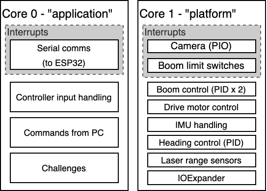
In this picture it looks like the platform core is much more busy, which may
well be the case (I haven’t measured it). However, handling the serial comms does
also consume quite a significant amount of time on the application core, and
the challenges' image processing can also be quite slow/expensive.
application implementation
The “application” code is relatively straightforward, and that’s one of the reasons for dividing the operation in half like this. At its core, it looks like a standard “game loop”, something like this pseudocode:
while True:
	input_events = get_input_events()
	for event in input_events:
		# Handle any controller input, feeding it to the current
		# task
		current_task.handle_input(event)

	# Get the latest status (sensors, boom position etc)
	# from the platform core
	platform_status = get_platform_status()

	# "Tick" the current task, to decide what action to take,
	# and take it
	current_task.tick(platform_status)

	# Wait some time
	sleep(0.01)
It just runs the same steps over and over again at a regular rate.
You can see that it has the concept of the “current_task”, which gets fed
controller events and platform status in order to decide what to do.
The most basic “task” would be the remote control one: If the thumbsticks on the controller are moved, set a corresponding motor speed. Simple!
Each autonomous challenge has its own “task”, which takes care of all of the challenge-specific decision making. Typically I’ve written these as state machines which break the task down into steps, and then use the sensor readings to decide when to move to the next “state” (drive towards trough, drop grain, return to barn…).
def cattle_tick(platform_status):
	if (state == DRIVE_TOWARDS_TROUGH) and
	   (platform_status.front_range < TROUGH_CLOSE_DISTANCE):
		platform.stop()
		state = DROP_RICE
	elif (state == DROP_RICE):
		platform.open_flap()
		state = WAIT_FOR_RICE
	...
I’ll go more into the specifics of each challenge in separate posts, but the tasks are defined so that their “tick” function is called regularly with the latest sensor readings etc, and they decide what to do based on that.
All of the actual “doing” is taken care of by the platform core. The
application task sends requests to the platform to do stuff, like
“move the boom to XX position”, “drive along this compass heading”,
“set a servo to this position”. The application only needs to decide what to
do, the platform makes it happen.
platform implementation
I could have used an existing RTOS implementation to provide me with multi-tasking and scheduling code, but I decided to just implement everything from scratch. No real reason, I guess I thought it would be fun. (And of course you get more control doing it yourself)
Unlike the application code which runs on a regular “tick”, the platform
code is entirely event-driven. It handles a large number of different tasks:
- Direct main motor PWM control
- Compass heading PID controller
- Boom homing
- Boom lift and extension PID controllers
- Boom trajectory planner
- Boom levelling servo controller
- Laser distance sensor triggering and reading
- IOExpander control (servos and sensors on the boom)
- Camera capture
All of which run at different times and different rates.
To handle this it uses an event loop, where operations can be scheduled to happen at some point in the future, and when that time comes they will get run. The operations are just arbitrary function calls, which has proven to be really handy for building things quickly.
Take the example of the boom levelling controller. Its job is to control the servo on the end of the boom to make sure that the attachment stays horizontal while the boom moves up and down. To do that, it runs regularly (every 20 ms to match the servo PWM frequency). Here’s the actual C code:
static void platform_level_servo_run(absolute_time_t scheduled, void *data)
{
	struct platform *platform = data;

	if (!__controllers_are_enabled(platform, CONTROLLER_BOOM_FORK_LEVEL)) {
		return;
	}

	int16_t angle;
	int ret = boom_lift_get_angle(&angle);
	if (ret != 0) {
		log_printf(&util_logger, "failed to get position");
		return;
	} else {
		int16_t servo_val = get_servo_val(angle);
		ioe_set_pwm_duty(&platform->ioe, 1, servo_val);
	}

	platform_schedule_function(platform, platform_level_servo_run,
	                           platform, get_absolute_time() + BOOM_SERVO_CONTROLLER_TICK);
}
Or in words, if you aren’t a computer/C programmer:
- If servo levelling has been disabled, just return. Don’t schedule any future work
- Otherwise, get the current angle of the boom
- Find out what PWM value is needed to match that angle
- Set the servo PWM value
- Schedule the function to run again in 20 ms
A similar set-up is used for all the other tasks.
For things like reading the laser distance sensors, they “trigger” a range reading, then need to wait for it to complete; so they schedule themselves to check again in a couple of milliseconds until the operation finishes.
This is all built on-top of the Pico C SDK’s “queue” and “alarm” functionality. The code is somewhat too big to paste onto this blog post, and there’s a few complications to deal with, but in essence:
- Whenever a task is scheduled, it sets up an “alarm” at the specified time. When the alarm “goes off”, it puts an event into the event queue, which gets handled in the platform main loop.
- The platform main loop just waits for something to arrive in the event queue, then does it.
You may wonder, why does the event queue exist? Why not run the scheduled tasks
from the “alarms” themselves? The reason for that, is that the alarm functions
run in an interrupt handler, and that can’t be changed. This means that they
can prevent other time-critical interrupt-driven tasks from running (like
handling the boom’s limit switches), and some of the
platform tasks like the inverse kinematics can take quite a long time.
Instead, it’s better to just put the event in the event queue from the
interrupt handler (which is fast), and then handle those (possibly long/slow)
tasks in the platform main loop.
Threading and synchronisation
Two cores means two threads, and there’s a classic old adage about multi-threading:
Some people, when confronted with a problem, think “I know, I’ll use multithreading”. Nothhw tpe yawrve o oblems.
Basically, if you have two things running code at the same time, then you need to be careful about them interacting with each other, lest they both try and write things on top of each other.
Maybe you’ve experienced this in the “real world” - say when you’re making food or tea with someone else, and you both mistakenly add salt/sugar without realising the other person had already done it - you had a synchronisation problem.
The event queue approach neatly bypasses this issue:
Everything that the platform code does is purely driven by the event
queue, and happens entirely sequentially in the platform main loop
The application code can never directly “look at” the internals of the
platform code, because the platform code could be updating them at the same
time and the application would see the wrong values.
Take the boom position for instance: There are two parts of the boom position,
the “X” coordinate and the “Y” coordinate. If the application code tried to
read them directly, it might do it at the same time as platform was
updating them, and see the wrong values:
time    platform thread              application thread
  |     ---------------              ------------------
  |     update X coordinate
  |                                  read X coordinate
  |                                  read Y coordinate
  |     update Y coordinate
  v
In the example above, the application thread read both X and Y in between the
platform code updating them - so now the application thread has the new
value for X but the old value for Y, and this can be a big problem.
Instead, all communication between the application and platform cores goes
through the event queue.
If the application wants platform to do something, it pushes an event into
the queue and it will get handled the same way as any other scheduled platform
task.
Taking the boom position example, if the application code wants to know the boom
position, it pushes a “get boom position” request into the queue, and platform
handles that request in-order, so it can never run at the same time as the
other platform tasks which handle the boom - so consistent values always get returned.
Because all of the events are handled sequentially in the platform loop, there’s never any problems with synchronisation or concurrent access, bypassing one of the major pitfalls of multi-threaded programming, and helping immensely in keeping complexity out of the interaction between the two cores.
Finally, time for some challenges
With this final piece in place, it’s time to write the challenge-specific code, using all the frameworks and building blocks that I’ve put together up until this point!